API RP 615: Valve Selection Guide
Download1. Scope
This Recommended Practice (RP) provides general guidance on valve selection for the hydrocarbon processing industry (HPI), which includes refineries and petrochemical, chemical, and liquefied natural gas (LNG) plants and their various associated processes. Selection guidance is provided for valve types covered by ASME B16.34 and API Valve Standards for the Downstream Segment, which include gate, ball, plug, butterfly, check, and globe valves.
Modulating control valves and pressure relief valves are outside the scope of this RP.
3. Considerations for Valve Selection
3.1 Valve Functions
Consideration of valve function:
一 stop flow (on-off or isolation valves referred to as block valves),
一 prevent flow reversal (check valves including stop-check valves),
一 regulate flow (control flow rate by throttling flow),
一 prevent overpressure in piping system (pressure relief valves—not in scope of this RP).
3.2 Valve Types
Consideration of primary valve types:
一 gate valves (API 600, API 602, API 603),
一 ball valves (API 608),
一 plug valves (API 599),
一 butterfly valves (API 609),
一 check valves (API 594, API 602),
一 globe/stop check valves (API 602, API 623).
3.3 Other Considerations
Other considerations to take into account:
一 pressure class and size;
一 fluid service;
一 materials of construction;
一 valve trim selection;
一 acceptable leakage rate;
一 valve special features such as fire testing, cavity venting, purge connections, etc.;
一 flow capacity and pressure loss;
一 cycle frequency.
4 Primary Valve Types
NOTE Some valve types are capable of performing multiple functions. If not used for their primary intended function, they may not perform well or may experience a premature failure.
4.1 Valves to Stop Flow or to Provide for Equipment Isolation (Block Valves)
4.1.1 Gate Valves
4.1.1.1 General
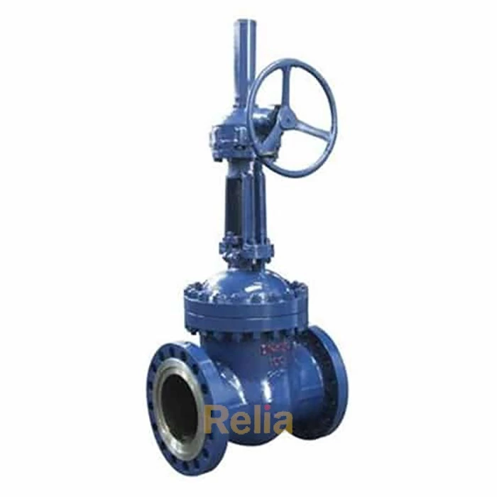
The gate valve is a common type of block valve for on-off service. The gate valve's closure member (gate) moves out of the flow stream perpendicular to the flow path. Typical process gate valves use a wedge type gate. Upon closing the gate to effect shutoff, the two faces of the gate engage the matching angle of the valve body seats. Turning the handwheel forces the disc firmly into the seats, which, assisted by line pressure, provides for shutoff of flow. The API standards covering gate valves are API 600, API 602, and API 603. Gate valves are typically not recommended for throttling service.
4.1.1.2 API 600 Gate Valves
API 600 covers sizes from NPS 1 and larger in pressure classes from Class 150 to Class 2500 with flanged or butt-welding ends. This standard was developed for refinery applications to provide a robust, heavy wall design suitable for service up to 538 °C (1000 °F). Pressure-temperature ratings for these valves are given in ASME B16.34 (standard class) for the listed materials. Body and bonnet wall thickness specified in API 600 are greater than those in ASME B16.34 thereby providing for an additional corrosion allowance capability. Stem diameters are also specified. The standard gate in API 600 is a one-piece, wedge-shaped, either solid or flexible wedge. The "flexible" wedge design provides for a small amount of angular deflection of the disc faces to provide for a better engagement with the body seats. This allows the wedge to accommodate some deviation from the ideal seat position caused by deflection of the valve body due to line stresses or thermal expansion, thereby resulting in improved seat tightness and reduced potential for gate binding in the closed position. See Annex A, Figure A.1 for a typical API 600 gate valve.
4.1.1.3 API 602 Gate Valves
API 602 covers the smaller gate valves in sizes up to NPS 4 for pressure classes from Class 150 to Class 1500 including Class 800. API 602 gate valves are commonly used in process plants in sizes from NPS I2 to NPS 2 in Class 800 with threaded or socket-welding ends. The standard port size is smaller than the line size but full port is an available option. These small valves are usually made from forgings. Flanged-end and butt-weld end valves are available where use of socket weld or threaded ends may not be desired, for example, in compressor lube oil service. See Annex A, Figure A.2 and Figure A.3 for typical examples of API 602 gate valves.
4.1.1.4 API 603 Gate Valves
API 603 was developed to provide a lower cost alternative to API 600 valves in corrosive, lower pressure services. They provide a lighter-weight, corrosion-resistant design made of a stainless or nickel alloy with a thinner body wall than API 600 valves. API 603 specifies wall thicknesses comparable to those in ASME B16.34. Like API 600, API 603 specifies minimum stem diameters. These valves are available in flanged or butt-weld ends in pressure Classes 150, 300, and 600 and in sizes NPS /2 anci larger. The wedge design is typically solid or flexible although split wedge and parallel-sided double disc gates are covered in the standard. Seat hardfacing may be desirable to reduce the galling tendency of stainless wedge seat faces to stainless body seat faces. See Annex A, Figure A.4 for an example of a gate valve from API 603.
4.1.1.5 Pressure Seal Bonnet Gate Valves
Gate valves with a special "pressure seal" bonnet closure design that avoids bonnet flanges are available from several manufacturers for Class 600 and higher and may typically be used in hydrogen service. The pressure seal bonnet design uses a compact body-bonnet joint that is pressure-assisted so that with increasing pressure the bonnet seals more tightly. The use of this design should be restricted to services that are not highly corrosive to avoid damage to the pressure seal element. Maintenance that involves reassembly of the pressure seal should be done with the help of a manufacturer's representative or a qualified valve repair organization to ensure proper assembly, testing, and preloading of the seal ring. Replacement seal rings may be available only from the original manufacturer. These valves are often supplied with weld ends thereby eliminating heavy line flanges. This valve design is not covered in API 600; however, it is covered in MSS SP-144.
4.1.1.6 Orientation Considerations
Although somewhat depending on pressure class and size, larger gate valves oriented in a position other than with the stem vertical may result with the disc getting hung up against the inside body guides such that the valve may get stuck, thereby rendering the valve inoperable. Special attention to guiding details including clearances, avoidance of sharp corners on the disc leading edge, and the use of machining/hardfacing on the guides is recommended. Even with the stem vertical, there may be an accumulation of dirt and other deposits between the seats such that the valve may not close fully. Installation of a bleed valve between the body seats to provide a purge connection can help remove such deposits.
4.1.1.7 Other Gate Valve Designs
Other gate valve designs used in process plants that are less common include double-disc designs for double block and bleed applications; "knife gate" designs for water, sludge, and other services with a high concentration of particulates; and "slide valve" designs typically used in high temperature, highly erosive fluid solids service such as in fluid cokers and catalytic cracking units. Class 150 and 300 knife gate valve designs are covered in MSS SP-135.
4.1.2 Ball Valves
4.1.2.1 General
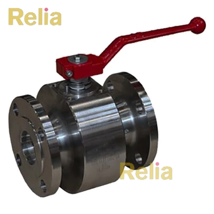
Ball valves are another valve type designed for on-off block valve operation. They are known as "quarter turn" valves, as a 90° turn (quarter turn) of the stem provides for full open to full closed position. Ball valves are typically not recommended for throttling service. Ball valves are available with both metallic and nonmetallic seats. Nonmetallic seats and seals can limit the pressure-temperature rating of the valve.
4.1.2.2 API 608 Ball Valves
API 608 covers ball valves for flanged and butt-welded ends in pressure Classes 150 through 600 and socket welded and threaded ends in Classes 150 through 800. Ports sizes covered include full bore, single reduced bore, and double reduced bore.
Ball valves are commonly categorized as either "floating ball" or "trunnion mounted" ball. In floating ball designs the ball is held in position (floats) between the upstream and downstream seats. Upstream pressure on the ball is the primary means of providing the seal on the downstream seat. In a trunnion mounted design, the ball is held in a fixed position by the valve body via a top and bottom stem / trunnion connection to the ball. Seat springs are used to load the seats against the ball, and line pressure also supplements the spring forces. Trunnion designs are typically found in higher pressure and larger bore applications. See Annex A, Figure A.5 and Figure A.6 for examples of API 608 ball valve designs.
4.1.2.3 Ball Valve Seats
Ball valves in API 608 are available with soft or metal seats, depending on service needs and temperature. At lower-temperature applications, soft seats are preferred when tight closure is required. API 608 defines minimum seat material pressure-temperature ratings for polytetrafluoroethylene (PTFE) and for reinforced PTFE. For other soft seat materials, the manufacturer should be consulted for the applicable pressure-temperature limits. Metal seated ball valves, often with a hardfacing on the seating surfaces, have been widely used in high temperature pressure service as well as applications exhibiting erosive/abrasive characteristics. In the case of manual operation, a gear operator is usually needed. Consideration should be given for the higher torque requirements of metal seated ball valves. Gear operators or actuators are commonly specified for valves > NPS 3.
Soft and metal seated API 608 valves can be specified as a "fire safe" or "fire tested" design. API 607 provides specific test requirements that would need to be satisfied to meet such specification, including subjecting a test valve to controlled fire conditions and measuring the leakage performance both during and after the burn.
4.1.2.4 Rising Stem Ball Valves
Rising stem ball valves utilize a rising or rising-rotating stem to rotate a ball a quarter turn and mechanically wedge the ball against a single seat to provide shutoff. They are either provided with manual operators or are automated with linear actuators. Rising stem ball valves may be used in molecular sieve switching; isomerization; thermal oil; and abrasive, dirty, and high-temperature services.
4.1.3 Plug Valves
4.1.3.1 General
Plug valves are designed for on-off service using a truncated cone-sealing element that is typically supported either by a thin grease film (lubricated plug) or by a polymer sleeve (sleeved plug). Some plug valve designs are metal seated to provide for higher temperature service. Plug valves are useful for tight shutoff applications and for highly corrosive/erosive services because of its large sealing area. Common plug valve types are covered in API 599, but there are other plug-type designs used for special applications. Plug valves are not recommended for throttling service.
4.1.3.2 API 599 Plug Valves
Sizes covered in API 599 are NPS /2 through 24 for flanged and butt-welding ends and NP§ /2 through 2 for threaded and socket-welding ends. This standard covers valves that have pressure-temperature ratings in accordance with ASME B16.34 Standard Class for steel and nickel-alloy body and cover materials, and ASME B16.42 for ductile iron. Lubricated plug valves and designs with nonmetallic components such as: seals, sleeves, liners, diaphragms, seats, and sealants may limit the applications of valves to more restricted pressures and temperatures. This pressure-temperature limit is to be marked on the valve nameplate. API 599 requires a temperature capability for lubricants and stem seals or packing to have a minimum temperature range of -29 °C (-20 °F) through 107 °C (225 °F). Nonlubricated plug valves may use metal seats as sealing elements or hydrocarbon-resistant plastic of elastomer sleeve linings. See Annex A, Figure A.7, Figure A.8, and Figure A.9 for examples of API 599 plug valves.
4.1.4 API 609 Butterfly Valves
4.1.4.1 General
Butterfly valves are defined in API 609 as two major types, Category A (see 4.1.4.2) and Category B (see 4.1.4.3). They are available in various designs and body/end configurations, including double-flanged and lug/wafer types. In addition to providing on-off
isolation, butterfly valves may also be suitable for flow regulation. Typical materials of construction include gray iron, ductile iron, bronze, steel, nickel-based alloys, and special alloys. These valves are intended for installation between flanges. For many butterfly valves, it is normal for the disc to protrude past the valve ends when in the open position. This may impact proper valve operation if the connecting piping is internally lined.
4.1.4.2 Category A Butterfly Valves
Category A butterfly valves typically have a concentric disc and seat configuration, with the pressure-temperature ratings assigned by the manufacturer with ASME Class 125 or Class 150 bolting patterns. Frequently specified for water and other utility services, these valves may be lined with a nonmetallic material that may also extend over the flange faces to serve as a gasket material. The seal on the seat relies on elastic deformation of the resilient seats as it closes. These valves are position seated and rely on stops to properly close or open, thus increasing the applied closing force may not improve sealing. See Annex A, Figure A.10 for a typical Category A Butterfly Valve.
4.1.4.3 Category B Butterfly Valves
Category B butterfly valves have pre-established pressure ratings, with a stem, disc, and seat design that is offset from the valve body centerline. This helps minimize rubbing and wear of the seating surfaces. Category B butterfly valves are typically used in sizes up to NPS 48 for lug and double-flanged designs and up to NPS 24 for wafer designs. The lug type or "single flanged" design has threaded bolting lugs as standard but optionally may be supplied with drilled through lugs. Double offset designs are position seated and commonly referred to as "high performance" type to distinguish from the torque seated triple offset type, where in addition to an offset stem and disc, the seat sealing angle is further offset from the valve centerline. See Annex A, Figure A.11 for a typical category B butterfly valve and Figure A. 12 for an example of a triple offset design.
Category B butterfly valves have a preferred seating direction dictated by the specific valve design. Double offset designs are typically soft seated. Triple offset designs may be metal seated, but more commonly are provided with a resilient metal/graphite laminated seat that helps these valves achieve tight closure.
4.1.4.4 Pressure-Temperature Rating
Pressure-temperature-rated butterfly valves that have an offset seat and either an eccentric or concentric disc configuration are typically available in Class 150, 300, and 600. These valves may have a seat rating less than the body rating. API 609 lists the minimum seat pressure-temperature ratings for PTFE and reinforced PTFE materials. Seat rating for other materials is determined by agreement with the manufacturer. The body rating is determined from ASME Standards B16.34 (standard class), B16.42 for ductile iron material, or B16.24 for cast copper alloys depending on the body material.
4.1.4.5 Orientation Considerations
Although butterfly valves are operable in any orientation, the preferred orientation for butterfly valves is with the stem horizontal to avoid debris collection leading to bearing contamination that may occur with the stem vertical.
4.2 Valves for Preventing Flow Reversal (Check Valves)
4.2.1 General
Check valves prevent undesirable backflow without any outside intervention. A typical application is for preventing backflow into a pump when the pump is shut down. Backflow could occur as a result of fluid pressure generated from the discharge side of another pump installed in parallel. Pump damage due to reverse flow could occur if such backflow is not prevented.
Check valves should be properly sized for the flow conditions to avoid mechanical damage resulting from continuous disc movement (opening and closing against the seats), which can occur if the flow is not sufficient to keep the disc fully open. This is more likely to be of concern with larger check valves (greater than NPS 2) having the same NPS as the line. To minimize wear or damage to internal parts, check valves should also not be located in areas of turbulent flow, such as adjacent to changes in pipe direction or near pump discharges. The manufacturer should be consulted for sizing guidance in low flow applications and for spacing guidance (both upstream and downstream) where turbulent flow is a concern.
Check valves may rely on any combination of (a) flow reversal, (b) gravity, (c) a compressed spring, or (d) an external force to close. They are typically metal seated and normally do not provide (and are not intended for) tight shutoff. However, some designs are more suitable for providing a tighter seal, particularly those that are also equipped with soft or resilient seats capable of achieving no leakage in the reverse direction.
The selection of check valves needs special consideration when used in pulsating flow service or unstable flow such as in reciprocating compressor service as they may open and shut rapidly as the flow rate changes. This may lead to hammering and valve damage. In such services, dual plate, tilting disc, and axial flow (nozzle) type check valves may provide some advantage over swing type because of their shorter stroke and typically lower mass of the closure element.
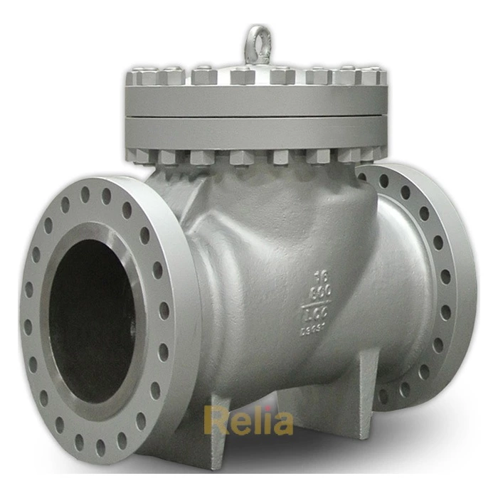
4.2.2 API 594 Check Valves
Check valves covered by API 594 include:
一 Type A—single or dual plate in wafer, lug, or double flanged designs;
— Type B—bolted bonnet, swing check valves with flanged or butt-welding ends.
Type A wafer, lug, or double flanged check valves include gray iron (ASME B16.1, Class 125 and 250), ductile iron (ASME B16.42, Class 150 and 300), and ASME B16.34 materials, Class 150 to 2500. These are available up to NPS 48 for Class 300 and lower. See Annex A, Figure A.13 and Figure A. 14 for examples of Type A check valves.
Type B swing check valves include ASME B16.34 materials in sizes up to NPS 24. These check valves provide for minimal pressure drop and turbulence as the disc is almost fully out of the flow stream in the full open position. See Annex A, Figure A. 15 for an example of a Type B swing check valve.
Body wall thickness for gray iron, ductile iron and ASME B16.34, Table 1, Group I materials are specified in API 594. These wall thicknesses match those in API 600 for gate valves. Wall thickness for materials in ASME B16.34, Groups 2 and 3 are as defined in B16.34.
4.2.3 API 602 Check Valves
API 602 covers check valves in the smaller sizes up to NPS 4 (piston, ball, and swing). Wall thicknesses are defined for pressure classes up to Class 1500. See Annex A, Figure A.16 and Figure A. 17 for examples of API 602 ball-and-piston check valves.
Some piston check designs (including stop check type) may have a space above the disc that can trap fluid and retard the opening movement of the disc. To permit unrestrained valve opening, pressure equalization from above the disc to the downstream end may be required to relieve pressure caused by the trapped fluid.
4.2.4 Stop-check Valves
Stop-check provide both check valve and globe valve functionality in one design where the piston-type disc can also be closed against the seat by mechanical means similar to that of a globe valve. Available in T-pattern, Y-pattern, and angle pattern, these valves function like a check valve in normal operation but can provide block valve capability when necessary.
4.2.5 Orientation Considerations
Proper orientation of a check valve is essential for correct operation. Most check valve designs are well suited for horizontal line installation. Swing-check valves with a bolted or welded cover in horizontal lines rely on gravity for the closure force, and thus should be oriented with the cover upwards. The valve's closure mechanism is designed to function as intended in this orientation. Swing-check valves installed with the cover turned to the side will not operate properly unless spring loaded by the manufacturer for this purpose. Likewise, dual-plate check valves in horizontal flow should be installed with the pins vertical.
Vertical line installation may require additional considerations. Downward flow vertical line orientation of API 594/API 602 type check valves should be avoided. Dual-plate check valves are well suited for upward flow vertical line installation, as both gravity and the internal spring assists closure. Similarly, Y-pattern as well as ball and piston type check valves that rely on an internal spring to close may be used for vertical lines with upward flow. Swing-type and tilt disc-type check valves may also be used in vertical lines with the flow upward, but their closure responses may be affected since the closing force due to gravity is reduced when the valves are in the open position.
4.2.6 Nonslam Check Valves
When a check valve closes on flow reversal, it is possible for a large surge force to develop due to the rapid momentum change of the stream acting against the closed valve. Fast-acting nonslam check valve designs are often specified in pulsating flow service for pump discharge applications so as to minimize the adverse effect of reverse fluid. Fast-acting check valves are ones with minimal closure member travel (e.g. the aerodynamic axial flow check valves, also known as nozzle check valves), small mass of the closure member (e.g. dual-plate check valves), and short distance between the center of rotation and center of the closure member (e.g. tilting disc types).
Although not in common use, some check valve designs may be fitted with an optional external device attached to the closure element to either assist or (in the case of large valves) dampen the effects of closure. Numerical simulations are sometimes used to predict the magnitude of a fluid surge pressure rise as affected by valve closure time to help determine the need for such devices.
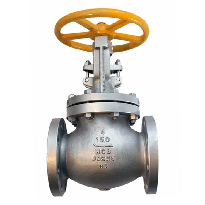
4.3 Valves for Throttling (Controlling) Flow—Globe Valves
4.3.1 General
The globe valve design is intended to control flow and may also be used as an isolation valve. The globe valve design minimizes seat wear during valve opening and closing as the disc moves toward and away from the body seat providing a uniform clearance and flow around the disc edge. Globe valves are typically used as manual bypass valves around engineered control valves to control flow when the control valve is blocked in and removed for repair. Globe valves are also used to take pressure drop in the system. Globe valves are covered in API 602 in sizes up to NPS 4 and in API 623 for sizes NPS 2 up to NPS 24. See Annex A, Figure A.18 and Figure A.19 for examples of globe valve designs.
4.3.2 Typical Sizes Available
Although larger sizes and higher-pressure ratings may be available, standard globe valves are typically available in sizes up to NPS 12 in Class 150, NPS 10 in Class 300, and NPS 8 in Class 600.
4.3.3 Globe Valve Sizing
Globe valves are suitable for throttling ideally when the disc is at least 20 % open; otherwise flow-induced vibration may result, leading to valve damage. For this reason, valve sizing is important to ensure that the valve is not too large for the intended flow condition. Typically, a bypass valve is too large if it is the same NPS size as the control valve it bypasses. For high differential pressure or critical throttling, a standard globe valve in bypass applications may not be suitable. An engineered control valve design should be considered in such applications.
4.3.4 Disc Guiding
For larger size and higher-pressure class valves, a provision to guide the disc throughout its travel should be considered. A guided disc is required by API 623 to ensure that the disc will not deflect or cock during travel, resulting in uneven seat wear and leakage.
Where conditions require the valve to be less than 20 % open, the use of a nonrotating or integral disc rather than the standard swivel disc should be considered as an option. This is to reduce harmful disc and stem vibration, but may result in accelerated seat wear and leakage.
5 Service Considerations
5.1 General
The majority of fluid services applicable to the process industry involve hydrocarbon streams of varying levels of corrosivity. These include streams that are considered to be either clean service, dirty service, or abrasive service, depending on the amount and type of suspended solids materials that could lead to valve plugging or erosion damage. Many of these streams also involve elevated temperatures. The presence of sulfur and other compounds in the streams in combination with elevated temperatures further contribute to a corrosive environment. Such streams require careful selection of materials to provide adequate service life. Corrosion engineers continue to study and develop materials to address these concerns.
5.2 Chlorine Service
Valves for chlorine service should be selected in accordance with the Chlorine Institute Pamphlet No. 6 Tiping Systems for Dry Chlorine."
Chlorine is highly corrosive, especially if water is present. Water combines with chlorine to form hydrochloric acid (HCL), which may corrode body and trim materials. Valves in chlorine gas or liquid service should be thoroughly cleaned and degreased to prevent the introduction of water, greases and oils, and other foreign material that could react with the process stream.
Chlorine has a high coefficient of thermal expansion that may result in a high increase in internal pressure if a liquid is trapped in the valve cavity between the valve closure member and the body seats. Valves in this service should incorporate a positive body cavity pressure relief feature.
5.3 Cryogenic (Low-temperature) Service
Valves used for cryogenic service are based on ASME B16.34 and API product standards, but with additional design features to ensure reliable operation at low temperatures. Such valves may also incorporate bonnet extensions to distance the packing and operating mechanism from the cryogenic fluid. This allows the stem packing to operate at a higher temperature and helps ensure that the valve operator is not exposed to severe cold or the hand wheel is not encased in ice while in service. MSS SP-134 provides additional details covering bonnet extension design. ISO 28921-1 provides both design details and testing requirements for low-temperature applications.
5.4 Hydrofluoric Acid Service
Valves in hydrofluoric (HF) acid service should be restricted to those types that have been demonstrated in service or by test to handle this service successfully. Generally, valve types that do not provide opportunities for the accumulation of solid matter are preferred. HF acid processes are operated under license from the technology owners who place strict controls on listed valves. The design and material requirements for these valves (typically carbon steel or solid Monel, with Monel or Hastelloy-C trim) as well as details of internal geometry are very specific and are designed to resist the specific characteristics of HF acid corrosion. Valves for this service are normally inspected and tested to a higher standard than those for typical process applications.
5.5 Hydrogen Service
Valves in hydrogen service may be forged or cast. Because hydrogen is an extremely permeable fluid and hydrogen service typically involves elevated temperatures, even small imperfections in the body casting may become a source of potential leakage. When cast, they are typically supplied with a higher casting quality as compared to commodity cast valves.
The selection and limitation of materials in hydrogen service is covered in API RP 941.
5.6 Oxygen Service
Valves in oxygen service should comply with CGA G4.4, Oxygen Pipeline and Piping Systems, as applicable. Valves for this service need to be thoroughly degreased, cleaned, assembled in clean conditions, and hermitically packaged and sealed. This is necessary to minimize accidental contamination during handling, transport and storage, as hydrocarbon based oils and greases are highly combustible in the presence of oxygen. For internal lubrication, silicon-based lubricants specifically formulated for oxygen service should be used. Additional guidance is available in CGA G4.1, Cleaning Equipment for Oxygen Service and MSS SP138, Quality Standard for Oxygen Cleaning of Valves and Fittings.
For oxygen service, valve body material selection is based on velocity and impingement considerations, and is typically carbon steel, stainless steel, or Alloy 400. Bronze or Monel trim materials are also recommended to prevent sparking and ignition as a result of high-energy mechanical impact.
5.7 Sour Service (Wet H2S Service)
Valve materials for sour service should comply with NACE MR 0103. This document, specific to downstream HPI processes, limits the hardness of metals; requires austenitic steels to be solution annealed; proscribes the use of certain materials for pressure retaining boundary parts (including valve stems); and provides special requirements for bolting, welding, etc.
NACE MR0103 places the responsibility on the user to specify whether bolts will be exposed to a H2S environment. Unless specified, external bolting may not be suitable for sour service. Where leakage of sour product is a concern, external bolting should also be in accordance with NACE MR0103. NACE compliant bolting is typically of lower strength than standard bolting. This may be a consideration when determining suitability of a valve for the design conditions, particularly if the original valve bolting is being replaced.
5.8 Viscous or Solidifying Service
Valves in viscous fluid service or solidifying fluid service, such as liquid sulfur or heavy fuel oil, often require external heating or steam jackets to maintain a sufficient temperature for valve operability. This is of particular importance with check valves, where sluggish response may be a concern.
6 Valve Material Selection
6.1 Body Material Selection
Material selection for valve body and bonnet for steel and nickel alloys are listed in Table 1 of ASME B16.34. This table is organized into three groups: Group 1 being ferrous materials, Group 2 austenitic stainless materials, and Group 3 nickel alloys relating to specific tables of pressure-temperature ratings. Other materials are covered in ASME B16.1 (cast iron), B16.24 (copper alloys), and B16.42 (ductile iron).
Particular attention needs to be given to the notes in these tables for limits concerning temperature and heat treatment. Reference to these pressure-temperature (P-T) tables provides the basis for selecting the proper pressure class to meet mechanical strength requirements. However, in addition material selection needs to consider resistance to the many material degradation mechanisms present in process flow streams such as general corrosion, stress cracking, low- and high-temperature effects, hydrogen service effects, etc.
6.2 Valve Trim Selection
6.2.1 General
Valve trim materials include more than just the valve seating surfaces as is well defined in trim tables contained in several API valve standards. In general, trim typically includes all internal parts in contact with the process fluid. If specific requirements are not defined, API standards require that trim materials shall be at least as corrosion resistant as the body material.
For gate valves, trim is defined as the seating surfaces of the closure member and body seats as well as the material of the stem and backseat bushing. A key consideration to avoid galling of valve seats is to provide either a difference in hardness between the mating seating surfaces or to provide hardfacing to both seating surfaces. Trim tables with various hardfacing options are provided in API 600 and API 602. Several of the available trims provide for hardfacing of one or both seating surfaces to better ensure long-term abrasion, corrosion, and wear resistance.
6.2.3 Trim for Other Valves
Globe valve trim is very similar to that of gate valves, with some parts not found in gate valves such as the disc retainer and (in some valves) a guide pin or guide rings. The same considerations of galling still apply. API 623 uses a similar trim table as API 600, and for small valves, API 602 covers both globe valves as well as gate valves.
For check valves, trim is defined as the seating surfaces of the closure member and body seat. A listing of acceptable trims is included in the API 594 trim table. Several of the available trims provide for hardfacing of one or both seating surfaces to better ensure long-term abrasion and corrosion. Most check valve designs do not experience significant sliding wear between seating surfaces, so the need for hardfacing both seating surfaces for wear resistance is not as critical as with other valve types.
For ball valves, trim is defined as the internal metal parts of the valve, such as the ball, stem, and metal seats or seat retainers. These are to be of the same nominal chemical composition as the shell and have mechanical and corrosion-resistance properties similar to those of the shell.
For butterfly valves, all materials in contact with the process fluid are to be the manufacturer's standard unless specified otherwise. Trim is defined as the seating surfaces of the body, disc, disc to shaft connection hardware (e.g. keys, pins, screws, etc.), and any internal fasteners that are in contact with the process fluid. However, trim material requirements are not explicitly specified. Shaft and bushing materials are also determined by the manufacturer taking into account the corrosion properties of the other trim components.
For plug valves, the corrosion resistance of the plug and stem material is required to be at least equal to that of the body material.
6.3 Seating Surfaces—Soft Seats
Ball valves and butterfly valves are often provided with resilient, nonmetallic seats to provide for zero leakage. To avoid the build-up of excessive body cavity pressures, pressure relief of the body cavity should be considered for soft-seated ball valves in liquid service.
API 608 and API 609 cover PTFE and reinforced PTFE materials with P-T ratings defined. Other soft seat materials are available with P-T ratings established by agreement between the purchaser and manufacturer. With PTFE material, the service temperature limit is typically 177 °C to 205 °C (350 °F to 400 °F).
6.4 Stem Sealing—Fugitive Emissions
Flexible graphite valve stem packing material is normally used in downstream process applications where high temperature and fire resistance is often a primary consideration. Although graphite material is susceptible to oxidation at temperatures above 343 °C (650 °F), it has been used with success in valves with service temperatures up to 538 °C (1000 °F) and even higher.
A typical flexible graphite packing design for gate valves is comprised of two to four rings of die-formed packing with one ring of reinforced braided material on top and one on the bottom of the packing stack. The braided material "wiper rings" help resist extrusion of the die-formed rings out of the stuffing box. Key material factors that affect flexible graphite packing performance are: percent carbon content, density of the packing, extent of impurities, and presence of corrosion/oxidation inhibitors. MSS SP-120 includes additional considerations for flexible graphite packing systems used in rising stem valves. To insure the quality of flexible graphite packing and minimize the risk of excessive fugitive emissions, API 622 provides a type-testing procedure for packing qualification and API 624 provides a type-testing procedure for rising stem valves equipped with flexible graphite packing.
Over time, packing sealing performance may degrade due to "packing consolidation." This results in the loss of gland load, leading to packing leakage. To minimize the potential for this to occur, the packing gland can be "live loaded" with conical washers on the gland bolting. When compressed, the conical disc washers can provide a means to maintain a gland load on the packing and help extend the amount of time over which the packing maintains an effective seal. MSS SP-143 provides guidance on proper design for live load packing arrangements.
Some quarter-turn valves may use elastomeric rings for stem seals. These seals may have a service temperature limitation lower than PTFE and are usually nonadjustable.
To further improve on fugitive emission performance, valves can also be supplied with a "bellows seal" on the stem in addition to a back-up packing gland. Bellows sealed valves are frequently used in steam service, as well as in certain hazardous/toxic applications. This packing design option is covered in API 602 for sizes NPS /2 to NPS 2. See Annex A, Figure A.20 for an illustration of a bellows stem seal from API 602.
6.5 Valve Bonnet Gaskets
For gate valves, API 600 and API 603 offer several options for bonnet gasket types: solid metal, jacketed metal, corrugated metal insert with graphite facings (Class 150 only), ring joint, spiral wound (Class 300 and higher), as well as a reinforced flexible graphite sheet for (Class 150 only) when approved by the purchaser. In all cases, the bonnet gasket is required to be suitable for a service temperature range of -29 °C to 538 °C (-20 °F to 1000 °F).
API 602 restricts the bonnet flange gasket to a spiral wound type with flexible graphite filler, unless specified otherwise. The design requirement confines the gasket to prevent overcompression and extrusion.
For globe valves, API 623 requirements are similar to API 600, except that only round bonnets are permitted. Flexible graphite sheet is not allowed, since the flat bonnet face permitted in API 600 is not used in API 623.
7 Valve Specific Features and Options
7.1 Valve Operation
Gate and globe valve operation is normally by means of a handwheel while quarter-turn valves have operating handles or levers in the smaller sizes. Quarter-turn valves with oval handles are available to prevent accidental operation that could occur if a lever was caught by loose clothing. Levers or handles are usually adequate for small, quarter-turn valves less than NPS 4, for example, but for larger valves, a means of assisted operation is often required. The number of times per year that a gate or globe valve is opened and closed should be considered as well. Valves larger than NPS 6 that are operated frequently would benefit from a gear operator installed. An important factor affecting the need for assisted operation (gear or power) is a limit on maximum rim pull force for ergonomic considerations.
Some valves such as metal-seated ball valves, triple offset valves, valves in high-pressure service, or valves operated frequently may necessitate gear or power actuation to assist with the high torque requirements. Installation of a bypass system can facilitate valve operation by reducing the effects of thermal shock or high differential pressures.
7.2 Position Indication
Whether a rising stem gate valve is open or closed is usually easily noted from the position of the stem relative to the yoke. Quarter-turn valves with operating handles properly mounted also provide a good visual indication. When gear drives are mounted on quarter-turn valves, it is important that the open and closed positions are clearly indicated with proper markings.
7.3 Hot Tap Valves
Valves used for hot-tapping warrant some special consideration. Two key requirements are that the valve port is large enough to pass the hot-tap cutter and that they are properly leak-tested in accordance with API 598 prior to installation. This is to ensure that the seat tightness is adequate to minimize leakage when the valve is closed and the cutting device removed.
7.4 Double Block Valves for Positive Isolation
Metal-seated valves in sizes larger than NPS 2 may not seal "bubble tight" when closed (as evidenced by the allowable leakage rates for new valves in API 598). When positive process stream isolation is needed for product segregation, the use of soft-seated valves is an effective solution, provided the seat material is adequate for the service temperature. For higher-temperature applications and for safety reasons, it may be necessary to use two block valves in series, with a bleeder between the valves. With two valves in series, any small leakage passing the first valve can be vented away with the bleeder to a safe location. When vented, the pressure between the two block valves is reduced to a low level, and the second valve is then likely to provide a good seal with little or no leakage. The need for this arrangement increases at higher pressures and with larger diameter valves.
7.5 Double Block-and-Bleed (DB&B) Valves (Single Valve)
Double-seated block valves may also provide the function of two block valves in series as described above when a vent connection is added between the upstream and downstream valve body seats. Leakage past the upstream seat can then be vented away by the bleed valve, thereby reducing the potential for downstream seat leakage.
Certain plug and ball valve designs are capable of providing double block-and-bleed functionality in a single valve configuration. Double block-and-bleed plug valves utilize two mechanically wedged resilient seals and a bleed system between the upstream and downstream seals to provide positive isolation and verification of positive isolation. They are often used for product segregation, tank storage isolation, and metering.
Standard API 600 gate valves are normally not designed to provide double block-and-bleed performance at full rated pressure, particularly in larger sizes and where a flexible wedge gate is provided. Other gate configurations, such as a solid- or split-wedge type, can improve the performance of the upstream seat. API 598 includes a special high-pressure closure test to confirm double block-and-bleed capability in a single valve.
7.6 “Fire Tested” Valves
Valves with seats, stem seals, or gaskets that are not capable of withstanding exposure to fire without failure could contribute to the severity of a fire by leaking flammable material. API 607 provides a type test for quarter turn valves and valves equipped with nonmetallic seats to confirm that adequate fire resistance is provided. Valves that successfully pass this test are considered Tire Tested" and are marked accordingly.
7.7 Valve End Connections
Valves larger than NPS 2 are typically furnished with flanged ends. This permits convenient installation and removal for maintenance or replacement. Since every flanged joint is a potential leak source, the use of butt-weld end valves should be considered in high pressure or hazardous services to minimize leak potential. Butt-weld ends are often used in high pressure hydrogen service.
Valves NPS 2 and smaller can be furnished with ends that are socket welded, threaded, butt-welded or flanged. For threaded end connections, the use of seal-welding for hydrocarbon and certain other services helps to provide better assurance against leaks in service.
7.8 Cavity Overpressure
Double-seated valves in the closed position may cause liquid to be trapped in the cavity between the seats. This could result from being in liquid service, condensation, or other means. Subsequent exposure to a temperature increase and consequent expansion of the trapped liquid medium could result in an excessive pressure buildup in the cavity sufficient to cause failure of the pressure boundary. A temperature increase caused by ambient heating could be sufficient to result in a failure and release of contents.
A positive body cavity relief feature, such as self-relieving seats or a vent hole drilled through the high-pressure side should be considered for such valves. Use of a drilled vent may render the valve to be unidirectional and therefore appropriate marking is required.
7.9 Flange Shields
Wafer valves (butterfly and check, for example) installed between a pair of flanges offer advantages in terms of cost and weight savings, but they have an increased potential for flange leakage. When exposed to fire conditions, differential expansion of the exposed bolts relative to the valve body may result in loss of gasket compression on the joint. This is a particular concern in hydrocarbon service where the leaking fluid can further intensify the fire. The use of flange shields, such as a stainless steel band around the flanges to cover the exposed bolts, will provide some degree of protection. Use of lug-type designs is an improvement; however, a double-flanged valve design is the preferred alternative as it minimizes the overall length of the individual bolts.
7.10 Valve Purge Connections
Gate valves in fouling/scaling service may accumulate dirt or debris between the seat rings preventing full disc closure. Large gate valves (NPS 12 and up), as well as valves installed with the stem vertical are particularly susceptible to such accumulation. NPS/4 or^arger valved connection installed between the seats in position G (see Figure 1 in ASME B16.34) will permit the use of a purge to help clear the obstruction.
Ball valves are also susceptible to the accumulation of dirt, debris, or particles such as coke in the valve cavity that can cause the valve to bind up or not seal. Ball valves can be provided with one or multiple purge connections (as recommended by the valve manufacturer.)
8 Steps for Valve Selection and Procurement
The following steps are recommended for consideration when selecting and procuring a valve appropriate for the intended service. Some steps may need to be recycled to address temperature or materials selection limits.
1) Determine required valve size and maximum design pressure and temperature for the process.
2) Select body material based on design temperature and corrosion resistance needs. (Materials are normally
selected from a material listed in the applicable ASME standard.)
3) Select valve type and governing API standard (API 600, 602, 603, etc.) based on required function.
4) Determine valve Class from pressure-temperature rating tables in ASME B16.34 (standard class), B16.1,
B16.24, B16.42, or applicable API standard, depending on the material and valve type.
5) Consider the need for special trim and temperature limits associated with nonmetallic seat materials.
6) Consider special packing needs.
7) Select desired valve end design (flanged, threaded, or welded).
8) For double-seated valves, define venting if needed to avoid cavity overpressure from trapped liquids.
9) Determine need for assisted operation (gear operator, motor drive, etc.).
10) Specify API 607 fire testing certification for valves with nonmetallic seats or seals in hydrocarbon service.
11) Determine the need for special testing requirements to API 598 (DB&B or Hot Tap Valves).
12) Review any special needs with company valve and materials specialists.
13) For critical valves, consider additional features, options, and suggested improvements with potential manufacturers.
14) Prepare a detailed purchase description to address purchaser specified requirements in accordance with the corresponding API standard. Annex B provides examples of typical purchase descriptions.