API RP 591: Process Valve Qualification Procedure
1 Scope
API RP 591 provides recommendations for evaluation of a valve manufacturer’s valve construction and quality management system for the purpose of determining a manufacturer’s capability to provide new valves manufactured in accordance with the applicable standards listed in Section 2. Testing per this RP that does not have an established requirement in the applicable standard is for information only.
Qualification of valves under API RP 591 is “manufacturing facility specific” and does not cover valves manufactured by other manufacturing facilities, whether owned by the same manufacturer or a third party.
5 Valve Qualification
5.1 Data to be Provided by Manufacturer
5.1.1 General assembly drawings of one valve size of each design for each pressure class shall be available to the qualification facility. These drawings shall show: all applicable construction details, including stem-to-wedge, disk, ball, or plug connections; guides; bearings; stem seals; body joint; body joint gasket; seat(s); and seal(s). They shall also include descriptions of the construction materials for all of the parts, including fasteners.
The valve manufacturer shall also identify the trim and sealing materials used.
5.1.2 Where welding, including casting repair, is performed by the manufacturer and/or the foundry on the valves being evaluated, the applicable welding procedures and weld procedure qualification shall be provided.
5.1.3 The manufacturer shall make available a tabulation of the foundries and forge shops from which castings or forgings used for bodies, bonnets, covers, and closure elements (e.g. wedges, disks, plugs, or balls) were obtained and the manufacturing facilities from which completed valves were obtained. The table shall include any special marking or coding used by the manufacturer to trace, distinguish, and identify component parts from different sources, including each manufacturing location and address.
5.1.4 For gate valve and globe valves, the manufacturer shall provide the recommended closure torques to adequately seat the valve at the maximum rated pressure for all sizes of valves being evaluated. For quarter-turn valves, the manufacturer shall provide break-to-open and end-to-close torques at the maximum rated pressure. For bidirectional valves, the manufacturer shall provide torque values for both directions.
5.1.5 The manufacturer shall provide written certification, signed by an officer or senior-level manager responsible for quality control for the manufacturing company, that states that the manufacturer’s production valves, regardless of size, pressure class, or materials of construction, are equivalent to the valves involved in the qualification and comply with the applicable product standards.
5.1.6 The manufacturer shall identify the name and location of the facility where the valves undergo final assembly and testing for inclusion in the final report required by 5.5.
5.1.7 Manufacturing by a third party (private labeling), where the manufacturing facility does not fully own the name, trademark, or symbol on the valve, requires that the following additional information shall be documented in the final report prepared by the test facility:
a) owning entity of the trademark, valve design, casting patterns, or forging dies;
b) entity responsible for implementing the facility’s QMS/quality control program; and
c) the business relationship between the manufacturing facility(s) and the trademark owner (valve supplier, joint venture, partial ownership, majority of controlling ownership).
A signed statement shall be included in the final report as required in 5.5.
5.2 Valve Qualification Facility
The manufacturer shall engage a qualification facility to perform the inspections, examinations, and tests described in this section. The facility(s) used shall be mutually agreeable to the purchaser and the manufacturer.
The qualification facility staff responsible for testing shall include a degreed or licensed
metallurgical engineer or mechanical engineer. The qualification facility may subcontract portions of these inspections, examinations, and tests as required; however, subcontracting back to the valve manufacturer is not permitted.
The qualification facility(s) shall be equipped and capable of performing or supervising the performance of nondestructive examination, physical tests, and chemical analyses on materials. The qualification facility staff shall be familiar with the applicable API valve standards and the codes, standards, and specifications referenced in those standards. The facility’s proposed program shall cover the following:
a) qualifications of the personnel performing the inspections and tests;
b) test details and format used to present the results of the tests;
c) number, sizes, and types of valves examined (see Annex A); and
d) source of the test valves and test valves selection method.
5.3 Selection of Valves
5.3.1 In order to ensure that the test valves were not made specifically for the tests, a random sampling feature shall be incorporated into the program. The qualification facility personnel shall select the test valves randomly from the manufacturer’s or distributor’s stock. Alternatively, the purchaser may choose to select the valves to be tested.
5.3.2 Random sampling shall include selection from each material category to be qualified per Annex A. It is expected that the manufacturer shall have sufficient stock from which a random sampling of their valve products and shell materials to be qualified may be selected. A reduced number of valves from the recommended sample lot may be agreed upon by the purchaser and manufacturer. Selected valves shall be clearly identified. Once testing commences, testing shall be limited to the randomly selected sample lot with no substitutions.
5.3.3 Casting and forging materials qualification of shell components shall be in accordance with Annex A.
5.3.4 For nonstandard or built-to-order valves, these may be provided directly from the manufacturing facility to the qualification facility as agreed to by the purchaser. Quantity and specific test requirements are to be as agreed by the purchaser.
5.4 Required Examination and Testing
5.4.1 All of the pressure tests specified in API 598, including the optional high- or low-pressure closure tests, shall be performed on each valve. Subsequently, the valve shall be opened at the maximum rated differential pressure. After the pressure has been relieved, the seating surfaces shall be checked for damage. The double block and bleed test is required for valves identified by the manufacturer as being double block and bleed capable.
The torque is to be applied by a calibrated torque wrench either directly or through a gear operator to the center of the stem/shaft. If the torque recommended by the manufacturer should prove to be inadequate, the torque may be increased incrementally to a maximum of 1.25 times the recommended value until the seat leakage is within allowable limits. The required closure torques shall be measured and reported. During seat tests, external forces that affect seat leakage shall not be applied to the valve ends.
Prior to the start of the qualification testing, gate and globe valves shall be stroked full open and closed with the stem in the horizontal position with flow orientation in both the horizontal and vertical directions to confirm operability unless these positions are restricted by the manufacturer. Results and restrictions shall be noted on the report.
5.4.2 Dimensions and finishes in Annex D, Table D.1, shall be measured on each valve, as applicable, and reported with those specified in the applicable standards and the manufacturer’s requirements.
5.4.3 All valve parts shall be visually examined to confirm compliance to applicable design standard and documented as listed in Annex D, Table D.2, as applicable.
5.4.4 After completion of required dimensional and visual examinations, paint and sealants shall be removed from the bodies, bonnets, and covers. Each of these valve pressure-containing components shall be visually examined to determine the following:
a) forgings or wrought materials are free from laps and seams; and
b) surface quality of castings, including the body, bonnet, and cover, is as specified in MSS SP-55.
After completing visual examination, a photograph of the disassembled valve parts, readable nameplate, and cast-in markings shall be made and conditions documented.
5.4.5 Material examinations listed in Table 1 shall be made on a minimum of five of the sample valves. The source of each body and bonnet (or cover) as well as each material category from each material source shall be sampled using a method that detects chemical composition. All detected elements are to be recorded (including all trace elements) using a method described in API RP 578. Chemical composition and hardness shall be non destructively determined except that small samples may be removed from the body, bonnet, or cover in a manner that will not affect the integrity of the component (e.g. areas such as bosses, ribs, and flange perimeters) and all trace elements detected by the test method used shall be reported. In addition, casting weld repairs and other pressure-containing welds shall have chemical composition and hardness Non destructively determined.
5.4.6 Strength tests of the stem/shaft-to-closure element connection shall be performed on valves as indicated in Annex A, in accordance with the requirements of Annex B.
The manufacturer shall make a guide for sizing the required test fixtures by providing the calculated stem/shaft- to-closure element failure loads for the valves to be tested available to the qualification facility conducting the strength tests.
5.4.7 All pressure-retaining welds shall be completely radiographed in accordance with the requirements of ASME B31.3 using the acceptance criteria for normal fluid service conditions. Butt-welding end preparations, welds in fabricated wedges, and pressure-retaining welds that cannot be radiographed shall be examined in accordance with ASME B16.34 by either the magnetic particle or the liquid penetrant method.
5.4.8 All cast valves in the sample lot of each casting type (investment and sand) and material category per 5.3.3 shall have 100 % of the pressure-containing components examined by radiography. A minimum of three valve pressure-containing components shall be examined from each foundry source. The procedure shall be in accordance with ASME B16.34, Appendix I-1. The qualification facility shall report each type of discontinuity for each film, with sketches illustrating the locations of all films. Casting quality shall be determined and reported for each valve (body, bonnet, cover, or end piece). The suggested minimum acceptable casting radiographic results are given in Annex C.
5.4.9 Pressure-containing components shall be magnetic particle or dye penetrant examined with acceptance criteria in accordance with ASME B16.34 Appendix II or III.
5.4.10 For valves employing handwheels, four hand wheels out of the sample lot shall be subjected to a hammer test. Using normal force, the hammer (3 lb [1.5 kg] for valves NPS 4 [DN100] and smaller, 10 lb [5 kg] for valves NPS 6 [DN150] and larger) should strike the outer rim between the spokes at an angle perpendicular to the plane of the hand wheel and any damage reported.
5.4.11 Each test hand wheel shall be subjected to a torque test, applying three times the torque recommended by the manufacturer for closure. In applying the torque, the handwheel is removed from the valve and the center of the handwheel tightly secured in an appropriate fixture. Torque is applied to the outer rim of the hand wheel at the spoke junction using an attachment mounted to the wrench. Any damage shall be reported.
5.4.12 Mechanical testing and metallurgical examination shall be made on the pressure-containing components of two valves. For API 602, welded bonnet valves, a cross-sectional dissection shall be performed to analyze and verify the strength of the weld as well as the presence and type of any mechanical body/bonnet connection (threads). If additional alloys are included in the test lot, one chrome moly sample and/or one austenitic stainless steel sample shall also be examined. Mechanical testing shall include tensile, yield, elongation, and reduction of area. For carbon and low-alloy steels, tests shall also include hardness and charpy impact testing. Charpy impact test temperature shall be performed at the lowest valve temperature rating.
Testing at other temperatures shall be agreed to by the purchaser. Microetch testing shall be conducted per ASTM A703 and shall include a 100× photomicrograph to assess the microstructure in accordance with ASTM E340. A wet-chemical, emission spectrometry, or equivalent analysis shall be made of these two samples and all elements, including trace elements, shall be noted. Duplex material shall have ferrite content verified and reported. Testing and examination results, as applicable, shall be compared to the appropriate ASTM standard and reported in the test report.
Annex A
(normative)
Selection Quantities for Examination and Test of Valves Made in Accordance with API Valve Standards
For each specified valve design, the minimum suggested sample lot is provided in Table A.2 through Table A.12.
For each NPS and class combination listed in the tables, the sample lot for each manufacturing plant location shall include at least three valves for each body and bonnet (or cover) source (foundry or forge shop), and three valves for each material category as defined in Table A.1.
Table A.1—Valve Selection Material Groups
| Material Group | Description | Type | Typical ASTM Designation | |||||
| Spec No. | Material Group | |||||||
| Group A | Carbon Steel | Cast | A216 | WCB WCC | ||||
| Forged | ASTM | A105 | ||||||
| Cast | A352 | LCB LCC | LC3 | |||||
| Forged | A350 | LF2 | LF3 | |||||
| Group B | Low-alloy steel | Cast | A217 | WC6 | WC9 | C5 | C12 | C12A |
| Forged | A182 | F11 | F22 | F5 | F9 | F91 | ||
| Group C | Austentic | Cast | A351 | CF8 | CF3 | CF8M | CF8C | CG8M |
| Forged | A182 | F304 | F304L | F316 | F316L | F347 F317 | ||
| Group D | Duplex | Cast | A995 | CD3MN | ||||
| Forged | A182 | F51 F53 F55 | ||||||
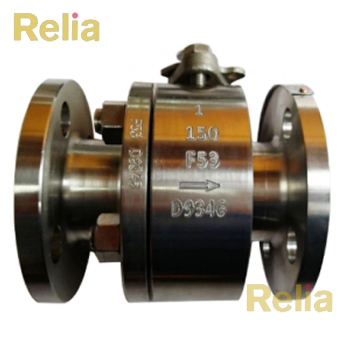
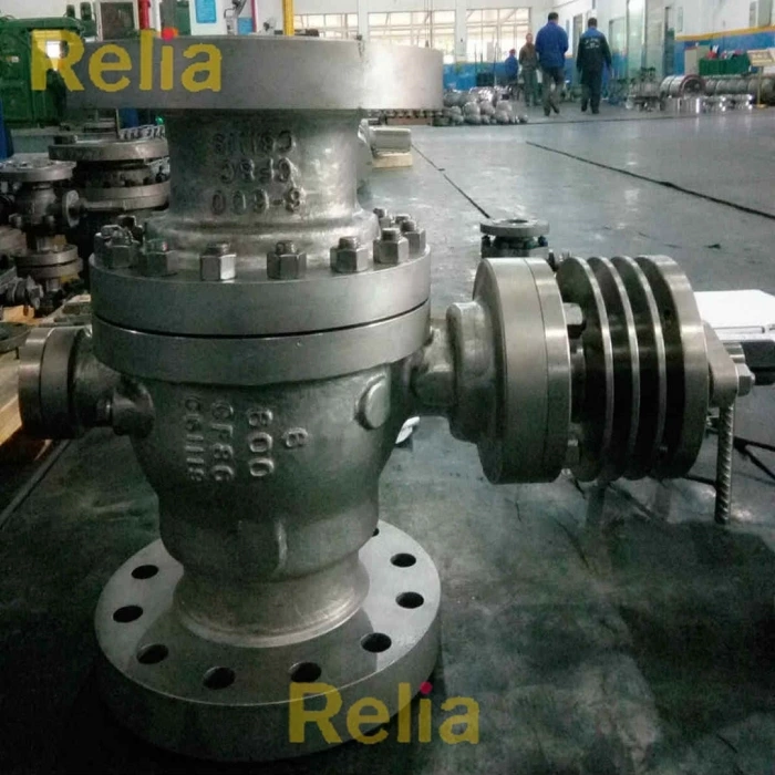
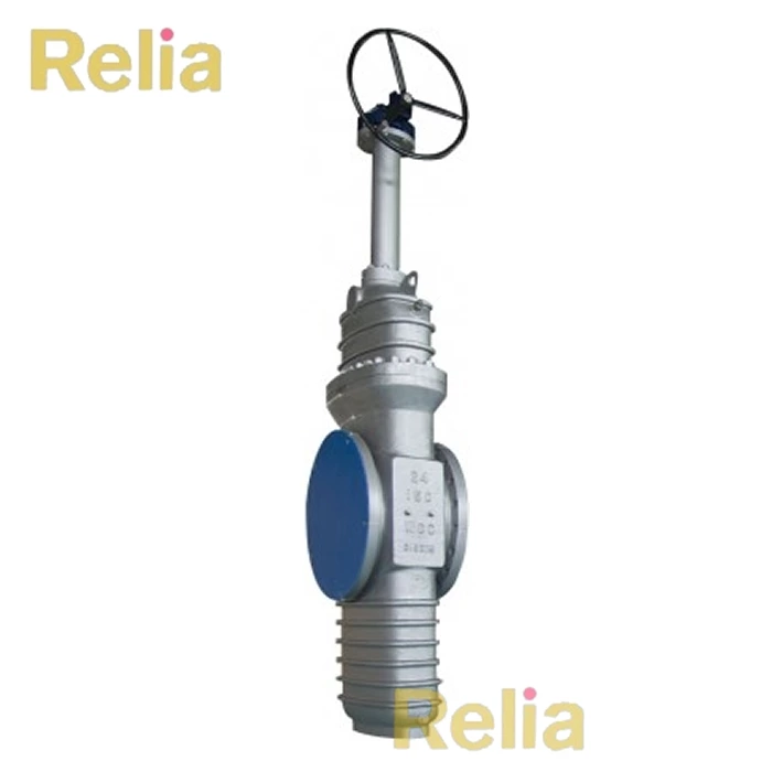
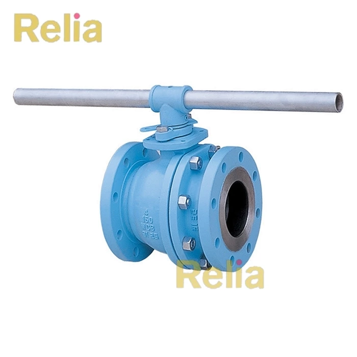
Related Product:
8 inch ball valve, 26 inch ball valve, 28 inch ball valve, 30 inch ball valve