API 6DSS: Specification for Subsea Pipeline Valves
API 6DSS specification defines the requirements for the design, manufacturing, quality control, assembly, testing, and
documentation of ball, check, gate, plug, and axial on–off valves for application in subsea pipeline systems for the
petroleum and natural gas industries.
This specification is not applicable to valves for pressure ratings exceeding Class 2500.
4 Valve Types and Configurations
4.1 Valve Types
4.1.1 General
NOTE Typical configurations of valves are shown in Annex B for illustration purposes only.
4.1.2 Gate Valves
Gate valves shall have an obturator that moves in a plane perpendicular to the direction of flow.
NOTE 1 The gate can be constructed of one piece for slab-gate valves or of two or more pieces for expanding-gate valves.
Gate valves shall be provided with a backseat or secondary stem sealing feature in addition to the primary stem seal.
NOTE 2 Typical configurations for gate valves with flanged and welding ends are shown, for illustration purposes only, in
Figure B.1 and Figure B.2.
4.1.3 Lubricated and Nonlubricated Plug Valves
Plug valves shall have a cylindrical or conical obturator that rotates about an axis perpendicular to the direction of flow.
NOTE Typical configurations for plug valves with flanged and welding ends are shown, for illustration purposes only, in
Figure B.3.
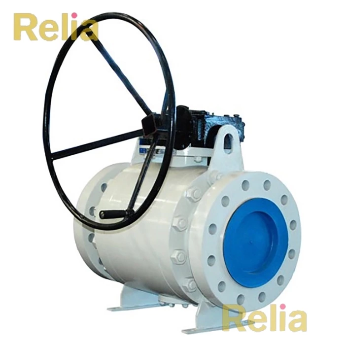
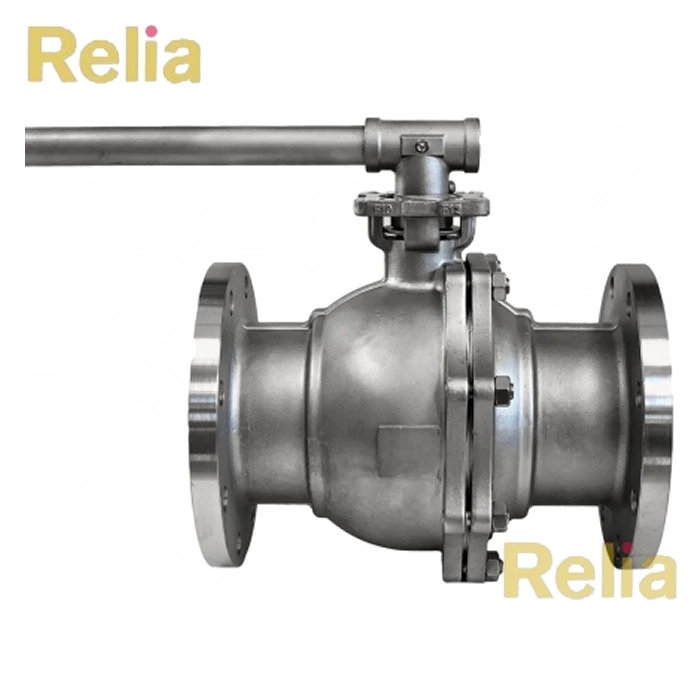
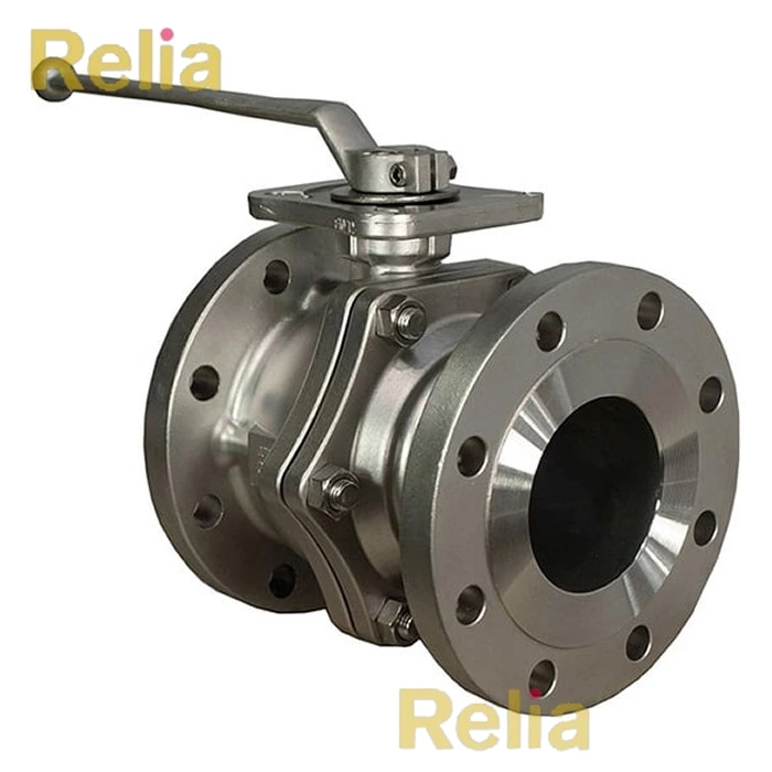
4.1.4 Ball Valves
Ball valves shall have a spherical obturator that rotates on an axis perpendicular to the direction of flow.
NOTE Typical configurations for ball valves with flanged or welding ends are shown, for illustration purposes only, in Figure B.4 to Figure B.6.
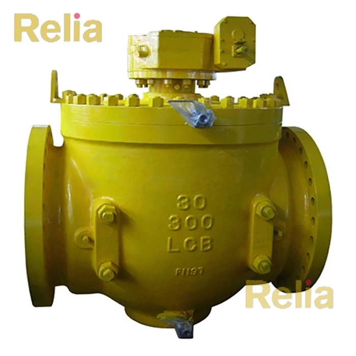
4.1.5 Check Valves
Check valves shall have an obturator that responds automatically to block fluid in one direction.
NOTE Typical configurations for swing and axial-flow check valves are shown, for illustration purposes only, in Figure B.7 to
Figure B.9.
4.1.6 Axial On–off Valves
Axial on–off valves shall have a cylindrical obturator that moves on an axis parallel to the direction of flow.
NOTE Typical configuration for axial on–off valves with flanged or welding ends is shown, for illustration purposes only, in
Figure B.1 0.