API 624: Type Testing of Rising Stem Valves for Fugitive Emissions
1 - Scope
API 624 standard specifies the requirements and acceptance criteria (100 ppmv) for fugitive emission type testing of rising stem valve and rising-rotating stem valves equipped with packing previously tested in accordance with API 622.
Packing shall be suitable for use at service temperatures –29 °C to 538 °C (–20 °F to 1000 °F). The type testing requirements contained herein are based upon elements of EPA Method 21.
Valves larger than NPS 24 or valves greater than class 1500 are outside the scope of this standard.
4 - Valve Selection and Test Preparation
4.1 The API 622 certificate or test report for the packing in the test valve shall be provided and attached to the API 624 fugitive emissions test report.
4.2 The test valve shall be completely assembled and ready for testing. The test valve shall be randomly selected from manufacturer or distributor stock where such stock is available. For valves not in stock, the manufacturer shall certify that the test valve was not modified in any way to meet type test requirements and is a typical representation of the manufacturer’s stock product. Valve selection shall be approved by the purchaser.
4.3 Body-bonnet and gland bolting torque shall be verified to be in accordance with published manufacturer’s installation specifications.
4.4 All pre-test activities to the valve shall be documented on the Fugitive Emissions Test Report in Annex A.
4.5 As a safety precaution, the air in the valve cavity shall be purged with an inert gas prior to starting the testing.
5 - Type Testing
5.1 The test medium used shall be methane 97 % minimum purity.
Caution—Methane used during testing is a pressurized flammable gas which requires that appropriate safety measures be taken.
5.1.1 Testing of valves is potentially hazardous and it is essential that the safety of personnel be given prime consideration. Given the nature of this test, hazardous release of pressurized gas could occur. Adequate shields or barriers in the area of the test enclosure and other appropriate means for the protection of personnel shall be provided.
5.1.2 The test facilities shall be designed to ensure that all the test conditions are conducted in a safe and protected environment. It is the responsibility of the testing facility to analyze the hazards resulting from the pressure and temperatures and take proper safety precautions. All applicable safety regulations shall be complied with.
5.1.3 All equipment shall have appropriate certification that verifies its suitability to withstand the minimum and maximum pressures and temperatures in the testing environment.
5.1.4 Hoses or pipes used for inlet and outlet supply of methane shall be suitable for maximum pressures and temperatures. Where hoses are used, appropriately designed restraints shall be used to prevent hose detachment from the test rig in the event that a blow-out occurs.
5.1.5 All testing shall be in accordance with local and national codes and regulations.
5.2 The stem orientation for a test valve shall be vertical.
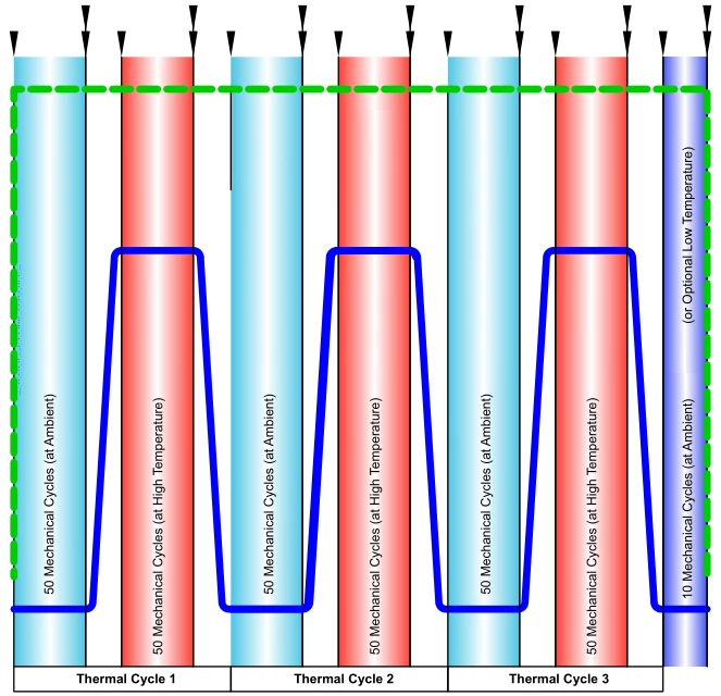
5.3 Valves shall be subjected to a total of 310 mechanical cycles and 3 thermal cycles per Figure 1. Mechanical cycling shall begin with the valve at ambient temperature. An optional low temperature test at –29 °C (–20 °F) may be performed if requested by the purchaser (see Figure 1).
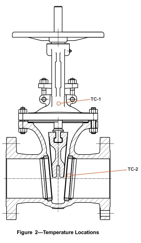
5.4 The valve shall be heated using an internal heat source or an external heat source such as electric heating blanket, coils, or other suitable equipment or an appropriate internal heat source.
5.5 The elevated test temperature shall be 260 °C (500 °F) ±5 percent.
5.6 The test pressure shall be the lower of 41.4 barg (600 psig) or the maximum allowable pressure at 260 °C (500 °F) per ASME B16.34 for the applicable material group and shall be held constant throughout the test.
Figure 1—Valve Cycling

6 - Acceptance Criteria
The Fugitive Emissions Test Report in Annex A shall indicate “pass” when the measured leakage throughout the test does not exceed 100 ppmv.
7 - Leak Test Equipment and Calibration
7.1 Monitoring equipment shall be as described below capable of providing on-board data logging with digital readout. The equipment shall be certified as intrinsically safe for use with the test medium. Data logging may also be performed with a separate data acquisition system.
7.2 The equipment shall meet the following performance requirements in the flame ionization mode:
a) Maximum variation: ±2 % at 100 ppmv.
b) Minimum detectable level (defined as 2 the peak noise): 300 ppb hexane.
c) Maximum response time to reach final value: 3 seconds.
d) Maximum recovery time to return to 10 % of initial value: 5 seconds.
e) Sample flow rate at probe inlet: 0.8 to 1.51 l/min (0.21 to 0.40 gal/min).
7.3 The test equipment shall be inspected prior to each use to ensure against fouling of the detector probe. This shall be done per EPA Method 21 using an external calibration gas with a known methane concentration.
To increase accuracy of readings between different measuring instruments and testers, the leakage device shall be calibrated to known leak rate standards daily prior to testing. A record of test equipment calibration shall be maintained by the test facility.
A porous or sintered metal/ceramic leak standard or similar device shall be used per the following procedure (see Figure 3):
a) Verify the sampling flow rate of the leakage monitoring device to be in the range of 0.5 to 1.5 l/min (0.13 to 0.40 gal/min) with a calibrated flow meter.
b) Verify the flow rate of the calibrated standard leak at a regulated differential pressure using 97 % minimum purity test gas. The calibrated standard leak shall be in the range of 0.025 to 0.075 ml/min ![]()
![]() of methane. The inverted beaker technique may be used with a sufficient amount of time to collect a measurable amount of sample. The test time should also be sufficient to fill the tubing and fittings used in the calibration setup.
of methane. The inverted beaker technique may be used with a sufficient amount of time to collect a measurable amount of sample. The test time should also be sufficient to fill the tubing and fittings used in the calibration setup.
10 - Valves Qualified
10.1 All valves of the same basic design as the test valve may be deemed to have been type tested, subject to the following additional limitations.
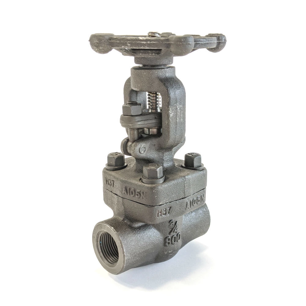
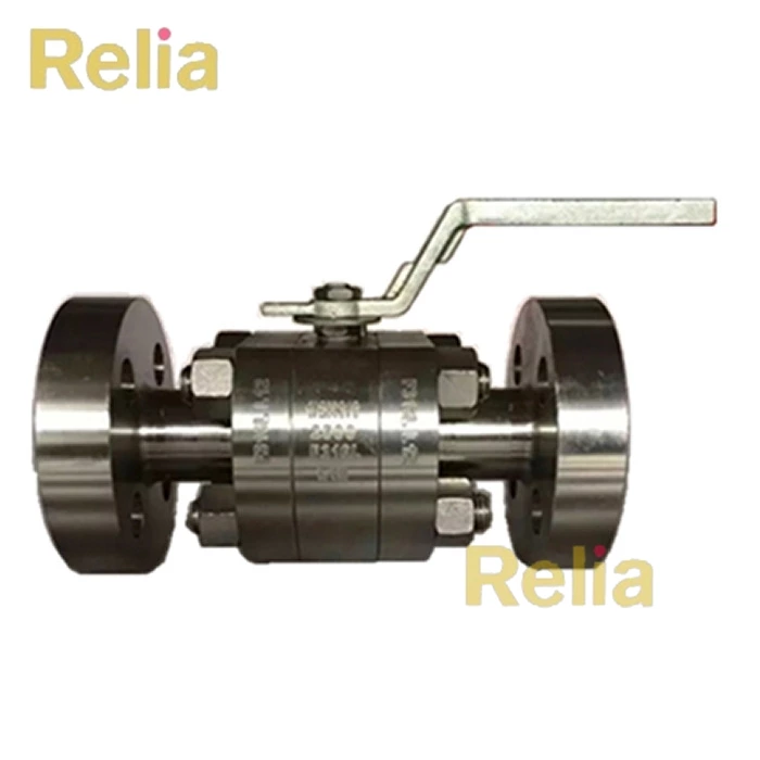
10.1.1 For API 602 valves, a NPS 3 / 4 class 800 test valve may be used to qualify all valves NPS 1 and smaller valves up to and including class 800. For API 602 valves, a NPS 1 1 / 2 class 800 test valve may be used to qualify all valves NPS 1 1 / 4 through NPS 2 1 / 2 up to and including class 800.
10.1.2 For API 602 valves, a NPS 3 / 4 class 1500 test valve may be used to qualify all valves NPS 1 and smaller in class 1500. For API 602 valves, a NPS 1 1 / 2 class 1500 test valve may be used to qualify all valves NPS 1 1 / 4 through NPS 2 1 / 2 in class 1500.
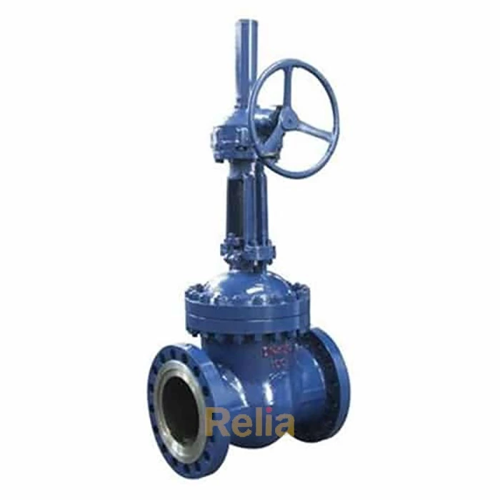
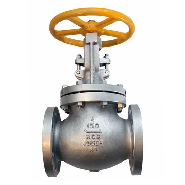
10.1.3 For all other valves:
10.1.3.1 NPS 4 qualifies all smaller diameters and one diameter larger and one pressure class lower than the test valve.
10.1.3.2 For valves larger than NPS 4, the test valve qualifies valves from two nominal sizes smaller to one nominal size larger and one pressure class lower than the test valve.
10.1.4 Annex B provides a list of valves that may be tested to qualify to this standard.
10.2 Any change in valve stem sealing system design including, but not limited to, packing material, packing manufacturer, or packing type/model requires a re-qualification.
10.3 If the location of the valve manufacturing facilities is different than what is listed on the API 624 certificate, the purchaser may request re-qualification.