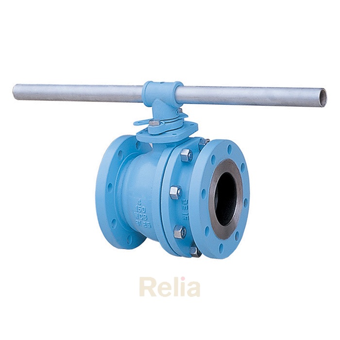
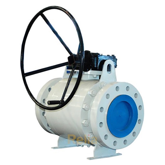
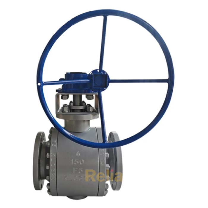
API 598 Ball Valve
API 598 Ball Valves: API 598 ball valves are rigorously inspected, examined, and pressure tested to the latest edition of the API 598 standard.
The following tests and examinations are to be done according to API 598 standard:
Shell test (1.5 times design pressure),
low-pressure closure test (0.6 MPa).
high-pressure closure test (1.1 times design pressure)
Zero leakage is required for all valves


The following tests and examinations for ball valves are to be done according to API 598 standard:
a) shell test,
b) low-pressure closure test,
c) high-pressure closure test,
Pressure Test of Ball Valve
| Test Description | Test Pressure |
| Shell | 1.5 times of design pressure |
| low-pressure closure | 0.6 MPa |
| high-pressure closure | 1.1 times of design pressure |
Duration of Test for Ball Valve
| Valve Size | Minimum Test Duration (Seconds) | |||
| DN | NPS (Inch) | Shell | low-pressure closure | high-pressure closure |
| ≤50 | ≤2 | 15 | 15 | 15 |
| 65 to 150 | 2-1/2 to 6 | 60 | 60 | 60 |
| 200 to 300 | 8 to 12 | 120 | 120 | 120 |
| ≥350 | ≥14 | 300 | 120 | 120 |
| The test duration is the period of inspection after the valve is fully prepared and is under full pressure. | ||||
6 Pressure Test Procedures
6.1 General
6.1.1 Valves designed to permit emergency or supplemental introduction of an injectable sealant to the seat area shall be tested with the injection system empty and not in use, except for lubricated plug valves.
6.1.2 When a liquid is used as the test fluid, the valve shall be essentially free from trapped air during the test.
6.1.3 Required protective coatings, such as paint, which may mask surface defects, shall not be applied to any surface before inspection or pressure testing. (Phosphatizing and similar chemical conversion processes used to protect valve surfaces are acceptable even if applied before the tests, provided that they will not seal off porosity.)
6.1.4 When closure testing valves, the valve manufacturer’s test procedure shall ensure that excessive force is not used to close the valve. The applied force may be determined from the appropriate figures in MSS SP-91, but in any case shall not exceed the values published by the valve manufacturer.
6.1.5 The valve shall be visually examined for leakage after it has been fully prepared and is under full test pressure.
6.3 Shell Test
Except as provided in 6.2.2, the shell test shall be made by applying the pressure inside the assembled valve with the valve ends closed, the valve partially open, and any packing gland tight enough to maintain the test pressure, thereby, except for bellows seal valves, testing the stuffing box.
6.4 Low-pressure Closure Test
6.4.1 The low-pressure closure test shall be performed with the seat sealing surface interface clean and free from oil, grease, and sealant. If necessary to prevent galling, the sealing surfaces may be coated with a film of oil that is not heavier than kerosene. This requirement does not apply to a valve that uses a lubricant as its primary seal (e.g.lubricated plug valves).
6.4.2 Any leakage at the seat sealing surface interface, behind the seat ring, or through the disk on the open side of the valve shall be detected when bubbles are observed coming from the closure (disk, seat, and seat ring), covered with water.
As an alternative, displacement measuring devices may be used, provided that the detectable leakage rate is equivalent to that given in Table 6, the valve manufacturer can demonstrate and validate that the procedure yields results equivalent to the requirements of this standard, and the device has been accepted by agreement between the purchaser and the manufacturer. Bubbler testing, when used for valves larger than DN 50 (NPS 2), shall only be acceptable when agreed to by the purchaser.
When volumetric devices (bubblers) are used to measure leakage, the test duration shall not begin until flow through the test tubing is established and stabilized. The device shall be calibrated to yield results equivalent to the units per minute listed in Table 6. Volumetric devices shall be calibrated with the same test fluid and at the same temperature as used for the production tests.
6.4.3 When closure testing gate valve, plug, and ball valves, a method of testing seat leakage shall be used that fills and fully pressurizes the body cavity to the test pressure between the seats and the bonnet area, as applicable, with the test fluid. This will ensure that no seat leakage can escape detection because of gradual filling of these volumes during the test period.
For a valve (other than a double block and bleed valve or globe valve) designed to close against pressure from either direction, the pressure shall be applied successively to each side of the closed valve with the other side open to the atmosphere to check for leakage at the atmospheric side of the closure. For a globe valve, pressure shall be applied in one direction with the pressure applied under the disk.
For a valve designed to close against pressure from one direction only and so marked, the pressure shall be applied on the pressure side of the valve only. For a check valve, the pressure shall be applied on the downstream side.
A closure test is required only in one direction for butterfly valves furnished with encapsulation or resilient internal liners and designed for use with Class 125 or Class 150 flanges (API 609, Category A valves). For other resilient-seated butterfly valves (API 609, Category B valves), the closure test is required in both directions. For butterfly valves with a preferred flow direction, the closure test in the nonpreferred direction shall be based on the reduced differential pressure rating in that direction.
6.4.4 Trapping test air or gas in the body cavity between the seats of a one-piece (solid or flexible) wedge gate valve and subsequently covering the seats with water or coating them with soap or a similar solution does not constitute an acceptable low-pressure closure test.
6.4.5 If a tapped connection in the body cavity is made to permit testing procedures described under double block and bleed valve in 6.6.1, the connection shall be in accordance with MSS SP-45 and shall be fitted before shipment with a solid pipe plug (in accordance with ASME B16.11) whose material composition is equivalent to that of the valve shell.
6.5 High-pressure Closure Test
The procedure for the high-pressure closure test shall be the same as the procedure for the low-pressure closure test except that, in the case of a liquid test, leakage shall be detected when drops, not bubbles as described in 6.4 are observed.
6.6 Double Block and Bleed High-pressure Closure Test
For a double block and bleed valve, the pressure shall be applied successively to each side of the closure through the valve port. Leakage into the body cavity shall be checked through an opening in the bottom of the valve (Position “G”per ASME B16.34). Where operational considerations do not allow for an opening in the bottom of the valve, an alternative opening location may be specified by the purchaser, and the valve shall be double block and bleed tested in a position that results in the alternative opening location being at the bottom of the valve during test. Testing in all positions and specifically in alternative positions will require procedures that meet the requirement of 6.1.2. Test duration shall be no less than twice (2×) the values provided in Table 5.
Leave Us Your Info
Could you please kindly fulfill the following information when enquiring:
Valve type (ball, gate, globe, check etc.), valve size, pressure class, valve material, and end connection (flanged, butt welding etc.)