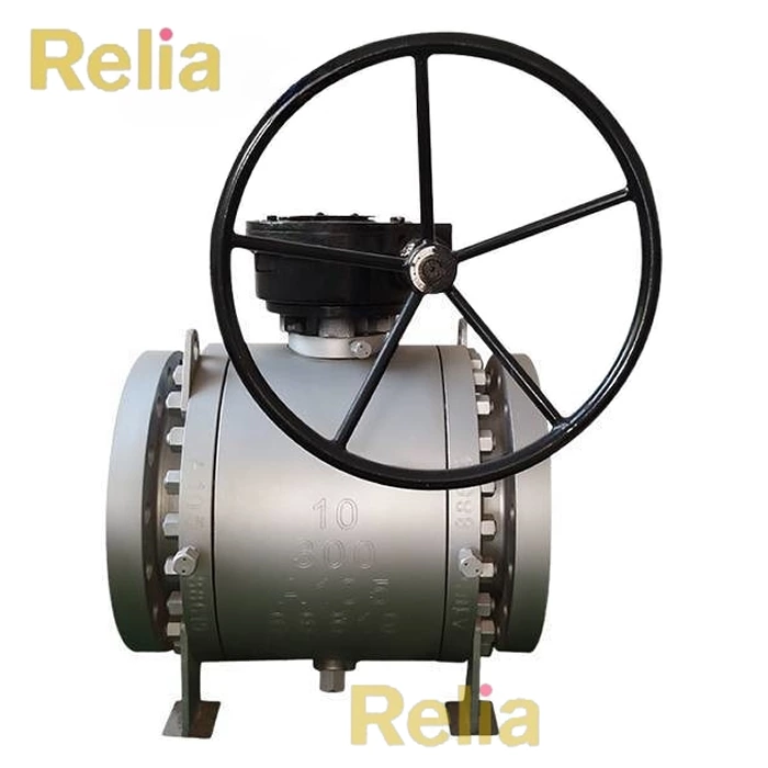
Trunnion Ball Valve
API 6D trunnion ball valves are engineered for high-performance applications in the oil, gas, and petrochemical industries. The trunnion ball valves in compliance with API 6D ensure robust design, material quality, rigorous testing, and traceability.
- Standard
- API 6D
- Size
- 2"-48"
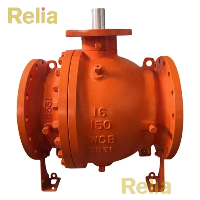
- Pressure Rating
- Class 150-2500
- Body Material
- Carbon Steel, Stainless/Duplex Steel, Etc.
- Certificate
- API 6D, API 607, CE


Structural Features
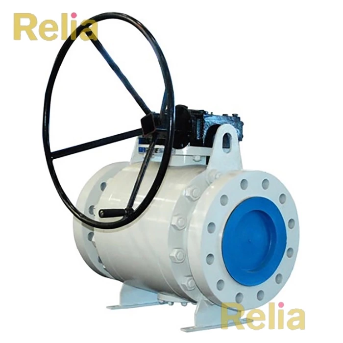
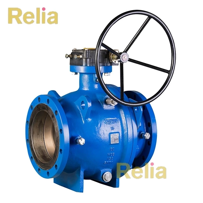
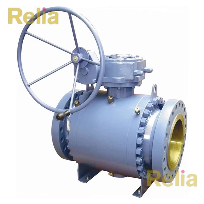
- Trunnion-Mounted Ball: The ball is fixed by two trunnion bearings, reducing operating torque and ensuring stability in high-pressure conditions.
- Sealing Mechanism: Utilizes bidirectional or unidirectional sealing, depending on application requirements. Common sealing materials include PTFE, reinforced polymers, or metal-to-metal designs.
- Actuation Options: Manual, gear-operated, electric, pneumatic, or hydraulic actuation.
Applications
- High-pressure differential systems
- Critical sealing applications (e.g., hydrocarbon pipelines)
- Extreme temperature environments (cryogenic or high-temperature)
- Oil and gas transmission pipelines
- Chemical processing and refining
Design Requirements
- Pressure-Temperature Ratings: Must comply with ASME B16.34 or equivalent standards.
- Sealing System: Design must prevent leakage under maximum pressure and temperature conditions.
- Fire-Safe Design: Optional fire-tested per API 607/6FA for valves used in flammable environments.
Material Requirements
- Body Materials: Carbon steel (e.g., ASTM A216 WCB), alloy steel (e.g., A352 LCC), stainless steel (e.g., A351 CF8M), or specialty alloys as per service conditions.
- Sealing Materials: PTFE, RPTFE, PEEK, or metal seals (for high-temperature/pressure applications).
- Fasteners: Bolts, nuts, and studs must meet API 20E/20F or equivalent standards.
Manufacturing and Testing
- Production Processes: Casting, forging, welding, and heat treatment must comply with API 6D and ASME standards.
- Non-Destructive Testing (NDT):
- Ultrasonic Testing (UT) for critical sections.
- Radiographic Testing (RT) for weld joints.
- Magnetic Particle (MT) or Liquid Penetrant Testing (PT) for surface defects.
- Pressure Testing:
- Shell Test: 1.5 times the rated pressure to verify structural integrity.
- Seat Test: Conducted with air or water at 1.1 times rated pressure to ensure zero leakage.
- Low-Pressure Closure Test: For bidirectional sealing validation.
Marking and Documentation
- Valve Identification: Must include manufacturer name, size, pressure class, material grade, serial number, and API 6D compliance mark.
- Required Documentation:
- Material Test Certificates (MTCs) for all components.
- NDT and pressure test reports.
- Compliance certificates (e.g., fire-safe, fugitive emissions).

Leave Us Your Info
Could you please kindly fulfill the following information when enquiring:
Valve type (ball, gate, globe, check etc.), valve size, pressure class, valve material, and end connection (flanged, butt welding etc.)