API 594: Check Valves- Flanged, Lug, Wafer, and Butt-welding
API 594 standard covers the design, material, face-to-face dimensions, pressure-temperature ratings, and examination,
inspection, and test requirements for two types of check valves.
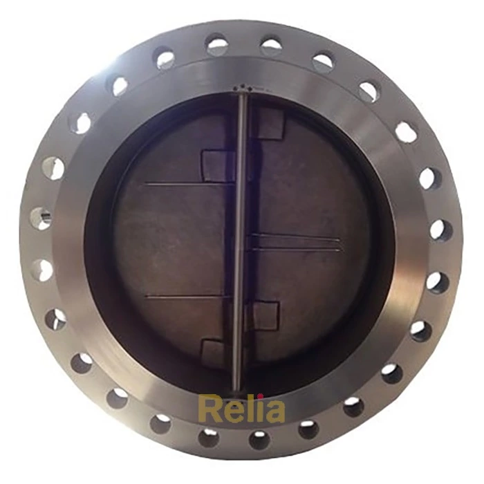
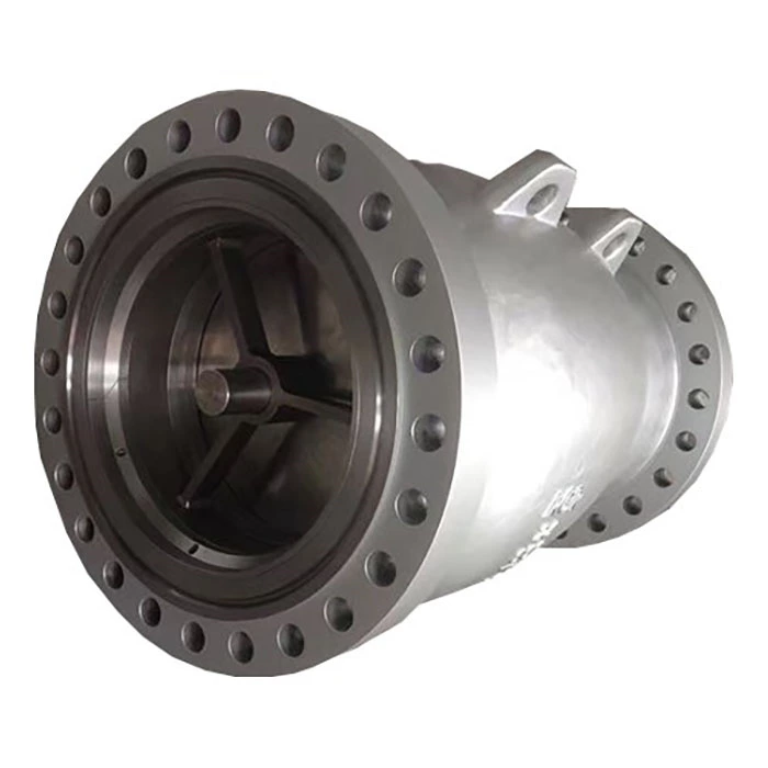
— Type “A” check valves are short face-to-face as defined in Table 2 and can be: wafer, lug, or double flanged; double flange as defined in Table 3; single plate or dual plate; gray iron, ductile iron, steel, nickel alloy, or other alloy designed for installation between Classes 125 and 250 gray iron flanges as specified in ASME B16.1, between Classes 150 and 300 ductile iron flanges as specified in ASME B16.42, between Classes 150 and 2500 flanges as specified in ASME B16.5, and between Classes 150 and 900 pipeline flanges as specified in MSS SP-44 or flanges as specified in ASME B16.47 Series A.
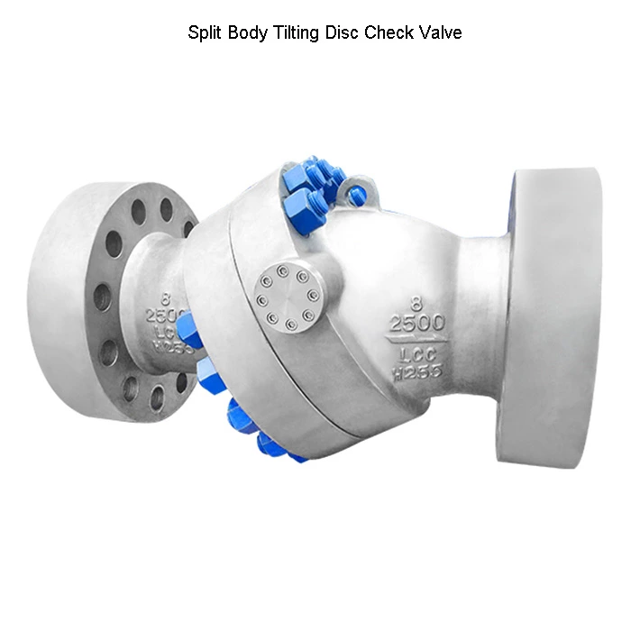
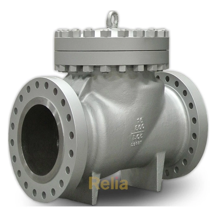
— Type “B” bolted cover swing check valves are long face-to-face as defined in 5.1.2 and can be: flanged or butt-welding ends of steel, nickel alloy, or other alloy material. End flanges shall be as specified in ASME B16.5, or ends shall be butt-welding as specified in ASME B16.25.
This standard covers the following ranges:
— Type “A” valves:
Classes 125 and 250, 50 ≤ DN ≤ 1200 (2 ≤ NPS ≤ 48) (excluding DN 90 [NPS 31/2]);
a) Classes 150 and 300, 50 ≥ DN ≤ 1200 (2 ≤ NPS ≤ 48)*;
b) Class 600, 50 ≤ DN ≤ 1050 (2 ≤ NPS ≤ 42)*;
c) Classes 900 and 1500, 50 ≤ DN ≤ 600 (2 ≤ NPS ≤ 24)*;
d) Class 2500, 50 ≤ DN ≤ 300 (2 ≤ NPS ≤ 12)*;
— Type “B” valves:
a) Classes 150 through 1500, 50 ≤ DN ≤ 600 (2 ≤ NPS ≤ 24)*;
b) Class 2500, 50 ≤ DN ≤ 300 (2 ≤ NPS ≤ 12)*.
NOTE- *Valve sizes DN 90 and DN 125 (NPS 31/2 and 5) are non-preferred sizes whose usage is discouraged.
— Sizes:
DN: 50, 65, 80, 100, 150, 200, 250, 300, 350, 400, 450, 500, 600, 750, 900, 1050, 1200;
corresponding to nominal pipe sizes (NPS):
NPS: 2, 21/2, 3, 4, 6, 8, 10, 12, 14, 16, 18, 20, 24, 30, 36, 42, 48.
Information to be specified by the purchaser is shown in Annex B.
API 594 standard nomenclature for valve parts is shown in Annex C. Figure C.1, Figure C.2, Figure C.3, and Figure C.4 illustrate typical Type “A” check valves, and Figure C.5 illustrates a typical Type “B” check valve. These figures show typical designs only and are not to be construed as precluding other available designs that comply with the requirements of this standard. The only purpose of these figures is to identify part names. The construction of a valve is acceptable only when it complies with this standard in all respects.