MSS SP-91: Guidelines for Manual Operation of Valves
0. PURPOSE
The purpose of MSS SP-91 Practice is to provide valve users with information for use in evaluating the manual operation of valves.
It must be understood that this information is general in nature and must be supplemented by specific operational data for the valve and service conditions to be experienced. The maximum and minimum torque ratings of specific valve and actuator types are not covered by this Standard Practice, but must be considered when applying manual input devices to any specific valve. Data from the valve and actuator manufacturers should be consulted regarding valve and actuator types and ratings.
1. SCOPE
MSS SP-91 Standard Practice provides guidelines for the operation of manually actuated valves as affected by the valve operator’s input.
2. DEFINITIONS
2.1 Manual Actuator
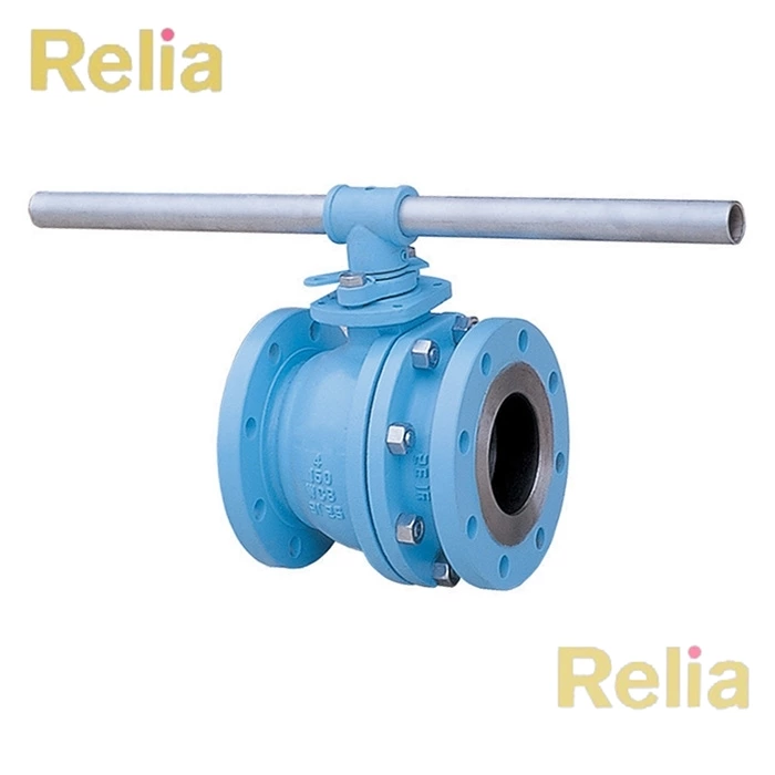
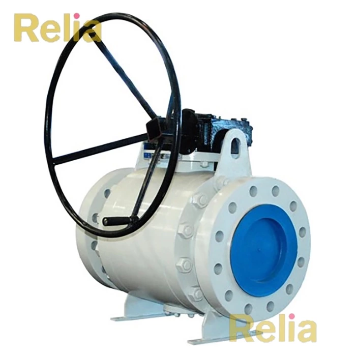
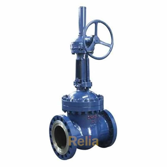
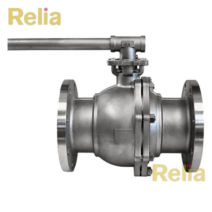
A device requiring manual force to provide the torque and/or thrust required to operate a valve, including levers, T-levers, T-chain-levers, handwheels, chainwheels, worm gear/spur gear/traveling nut units, and manual override units on power actuators.
2.2 Manual-Impact Device
A hammerblow handwheel or chainwheel device that momentarily increases the breakloose seating and unseating torque capability of handwheels or chainwheels by the application of impact forces.
2.3 Power Actuator
A mechanism for actuating valves using other than manual input to apply force or energy, such as pneumatic, electric, and hydraulic units.
2.4 Operator
Person or persons who apply manual force to an actuating device. A typical operator is one who is capable of exerting approxiamately 150 pounds of force (670 N) on a lever with an effective length of 12 inches (300 mm) at waist level. If the intended operators or the system requirements differ, specific information should be obtained from the valve supplier.
2.5 Effective Lever or Effective T-Lever Length
The actual lever length measured from the stem-center to the center of force application, 1 1/2 inches (38 mm) from the lever end, or the total T-lever length less 3 inches (76 mm).
2.6 Effective T-Chain-Lever Length
The length from stem center to the center of the chain attachment multiplied by the sine of the angle included between lever and chain in the position under consideration.
2.7 Available Lever Torque
The product of a force exerted on a lever at the effective lever-length, multiplied by the effective lever-length.
2.8 Handwheel Rim-Force
The total rim-force exerted on the rim of a handwheel or on the spokes of a capstan handwheel, which is the sum of a push- and-pull force.
2.9 Available Handwheel Torque
A product of the handwheel rim force multiplied by the handwheel radius (handwheel diameter divided by 2), or if a capstan handwheel, spoke forces multiplied by the length of one spoke, measured from the center of the handwheel less 1 1/2 inches (38 mm).
2.10 T-Chain-Lever or Chainwheel Torque
The product of the total pull force exerted by the operator multiplied by the chainwheel radius (effective chainwheel diameter divided by 2) or multiplied by the effective T-chain lever length.
2.11 Normal Operating Conditions
This refers to the conditions experienced by one operator when attempting to apply force to an actuating device.
Normal conditions are with the manual actuator at waist level and the plane of rotation of the lever, handwheel, or chainwheel located vertically or horizontally, with temperature at 70 0 F (20 0 C), good footing, and with no space restrictions.
2.12 Momentary Force
If an operator must apply a high force to a manual actuator to cause a valve to break loose, but may exert relatively lower forces to continue actuation of the valve, the initial high force is referred to as a momentary force.
2.13 Short-Term Force
The force an operator could be expected to exert on an actuating device for a small portion of the total valve travel such as for seating and unseating.
2.14 Uniform Force
The force that an operator could be expected to exert for a period of up to 5 minutes. May be used on certain valves that require an operator to exert a relatively constant force on an actuating device throughout the valve travel.
2.15 Long-Term Force
The force an operator could be expected to exert on an actuating device for extended periods of time.
2.16 Valve Operating Characteristics
Forces developed on the valve stem, hence the actuator, during the closed-open-closed operating cycle are indicated in terms of:
2.16.1 Torque
A turning moment developed on stems of valves such as quarter-turn ball, plug, and butterfly or on the stem nuts of globe or gate valves.
2.16.2 Thrust
Axial force developed on valve stems, such as globe or gate valves.
2.17 Net Mechanical Advantage
A multiplying factor for gearing that includes both the gear ratio and the efficiency of the device.