BS 6364: Cryogenic Valves Specification
BS6364 Standard specifies the requirements for the design, manufacture and testing of valves for cryogenic service.
The size range covered by this standard is DN 15 to a maximum nominal size appropriate to the above product standards, in the temperature range – 50 °C to – 196 °C, yet capable ofoperation at ambient conditions to allow for start-up and run-down.
Table 1 — Minimum gland extension length for cold box applications
| Type | Minimum gland extension length ( in mm) for nominal size DN: | ||||||||||||||
| 15 | 20 | 25 | 38 | 50 | 80 | 100 | 150 | 200 | 250 | 300 | 350 | 400 | 450 | 500 | |
| Globe | 500 | 500 | 500 | 600 | 600 | 700 | 700 | 700 | 750 | 850 | 850 | — | — | — | — |
| Gate | 500 | 500 | 500 | 600 | 600 | 700 | 700 | 700 | 900 | 1000 | 1100 | 1200 | 1300 | 1400 | 1500 |
| Ball | 500 | 500 | 500 | 600 | 600 | 700 | 700 | — | — | — | — | — | — | — | — |
| Butterfly | — | — | — | — | — | — | 700 | 700 | 700 | 750 | 800 | 850 | 850 | 900 | 950 |
Note: BS 6364 table 1 specifies the the length of extended bonnet for cryogenic valves.
4 - Requirements
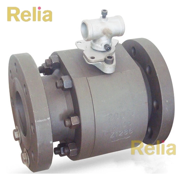
4.1 Valves shall be supplied with extended bonnets/glands (see Figure 1). The length of the extension shall be sufficient to maintain the stem packing at a temperature high enough to permit operation within the normal temperature range of the packing material.
4.2 Valves on gas service shall be capable of operation with the valve stem at or above the horizontal position.
4.3 Valves in liquid service other than cold box applications shall be capable of operation with the valve stem at or above 45° above the horizontal position.
4.4 For cold box applications, valves shall be suitable for use with the valve stem at or above 15° above the horizontal position and in addition the minimum gland extension length as shown in Figure 1 shall be as given in Table 1.
NOTE - If any special length of gland extension is required by the purchaser he should state this (see Appendix C).
4.5 For applications other than cold box applications the minimum gland extension length shall be 250 mm (see Figure 1).
4.6 Valves shall be designed to relieve pressures above normal workingpressure that may build up in trapped cavities due to thermal expansion or evaporation of liquid.
NOTE - For ball and gate valves this requirement can be met by the provision ofa pressure reliefhole or passage or other means, e.g. pressure relieving seats, to relieve pressure in the bonnet and body cavities to the upstream side of the valve. The means adopted will be determined by the manufacturer unless the purchaser exercises his option in accordance with Appendix C.
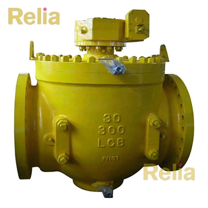
4.7 Where valves, by design, are unidirectional in operation, the flow direction shall be clearly indicated either on and integral with the body of the valve or on a plate securely attached to the body of the valve.
In the design of such valves, measures shall be taken to prevent incorrect assembly.
4.8 Valve bonnets shall be bolted, welded or union type. Union type bonnets shall only be used on valves DN 50 and below, or for marine applications DN 40 and below, and the union nut shall be locked to the body. The use of screwed bonnets shall not be permitted.
NOTE - Gasket materials for bolted bonnets are outside the scope of this standard (see Appendix C).
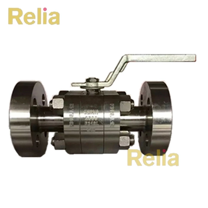
4.9 For steel valves, fabricated gland extensions shall be constructed from a single length of seamless tube butt-welded to the bonnet and gland housing.
4.10 For high pressure bronze or copper alloy valves of PN 100 rating or greater, the extension tube shall be screwed into the bonnet prior to silver soldering.
4.11 The clearance between the valve stem and gland extension bore shall be designed to minimize convection heat losses. The wall thickness of the extension shall be minimized, compatible with the rating of the valve and mechanical strength
requirements in order to reduce conduction heat losses.
4.12 Valve stems shall be of one-piece construction except for end entry ball valves, in which case the valve design shall be such that the valve stem cannot be blown out of the body in the event of the gland being removed while the valve is under
pressure. Rising stem valves with renewable gland packing that incorporate a back seat shall have the back seat located in the region of the gland.
Gland designs incorporating lantern rings and screwed plugs in the gland body shall not be used.
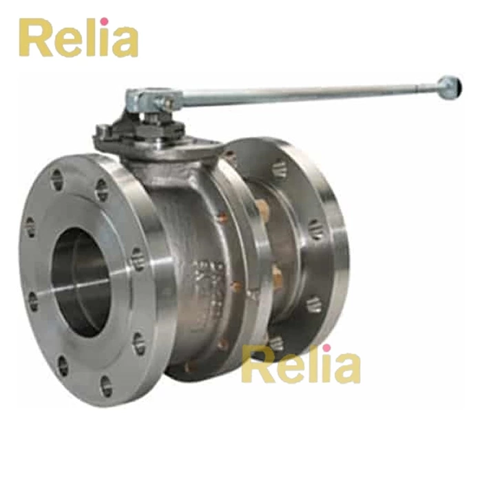
4.13 Globe valves shall have tapered or conical discs. The use of flat seated discs shall not be permitted.
4.14 The maximum force required to operate the valves manually under service conditions, when applied at the rim of the handwheel or lever, shall not exceed 350 N, except for valve seating and unseating only, when it shall be permissible for this
value to be increased to 500 N. Where reduction gearing is provided, it shall be suitable for operation at ambient temperature.
4.15 Valves for flammable service shall be designed to ensure electrical continuity to prevent build-up of static electricity.
5 Materials
NOTE - The specification of materials and gland packing is outside the scope of this standard owing to the variety of materials for the temperature range of operation, but Appendix B gives the preferred austenitic steels and non-ferrous materials that may be used.
5.1 Bolting materials shall be selected from those listed in BS 4882.
NOTE - Note that on first cooling below ambient temperature and down to – 196 °C, some austenitic steels increase slightly in size owing to a permanent metallurgical change. This may result, for example, in bolts relaxing their pre-load the first time they are cooled. The manufacturer/user should take account of this in selecting the steels used.
5.2 Valves shall have metal/metal or soft seats (see Appendix C). Soft seats shall be backed by a secondary metal seat. Virgin PTFE shall be supported in such a way as to prevent cold flow.
5.3 The valve trim materials selected shall be such as to avoid the effects ofgalling (seizure or binding) caused by frequent operation at cryogenic temperatures.
8 Pressure testing
8.1 Shell strength test
8.1.1 The valve body and bonnet shall be subjected to a hydrostatic or pneumatic test. Hydrostatic testing shall be carried out as described in the appropriate standard(s) given in clause 1. For stainless steel valves, the chloride content of the water for hydrostatic tests shall not exceed 30 p.p.m. Pneumatic tests shall be at the full test pressure specified in the appropriate valve product standard.
WARNING. - Attention is drawn to the hazardous nature of pneumatic testing.
8.1.2 For shell tests, discs and wedges, iffitted, shall be in the open position and ball valves shall be in the half-open position.
8.1.3 After hydrostatic shell testing, the component parts of the valve shall be thoroughly cleaned and degreased.
8.2 Shell leak test. After the hydrostatic or pneumatic strength test, body and bonnet joints and glands of valves shall be soap or immersion-under-water tested using dry oil-free air or nitrogen at the full seat rating of the valve.
The stem shall be free to turn at this pressure.
During the test duration specified in Appendix B of BS 6755-1:1986, there shall be no visible leakage.
8.3 Seat leak test
8.3.1 Valve seats shall be tested with dry oil-free air or inert gas at the full seat rating or for ball valves at 6.9 bar 1) Valve shut-off shall be achieved by the normal methods of operation and duration of tests shall be in accordance with BS 6755-1.
8.3.2 For valves having metal-to-metal seats, the maximum permitted leakage rate shall be 0.3 mm 3 /s ° DN.
8.3.3 For valves having soft seats there shall be no visible leakage for the duration of the test. 8.4 Cryogenic prototype testing. When tested as described in Appendix A, valves shall satisfy all the requirements of the test as given in that appendix.
Valves intended for marine applications shall be subjected to the tests described in Appendix A.
NOTE - For all other applications, cryogenic testing is normally carried out only when requested by the purchaser and it is
essential, therefore, for the purchaser to state he requires this testing to be done end also, whether he wishes to be present
(see Appendix C).
Appendix A - Cryogenic test
A.1 Temperature. The cryogenic test temperature shall be – 196 °C.
A.2 Prior to testing
A.2.1 Degrease the valve components, dry them and assemble the valve in a clean and dust- and grease-free environment.
A.2.2 Tighten bolts to a pre-determined torque or tension and record the value.
A.2.3 Make suitable thermocouple connections to the valve to enable valve body and bonnet temperature to be monitored throughout the test.
A.3 Testing
A.3.1 Handwheel operated valves: gate, globe, ball and butterfly valves
A.3.1.1 A suitable test apparatus is shown diagrammatically in Figure 2. Set up the valve as shown in Figure 2 in the test tank and make all connections. Take care to ensure that the valve gland is positioned clear of the cold boil-offgas in the top of the tank.
A.3.1.2 Make an initial system proving test at the maximum seat test pressure [see A.3.1.4 d)] at ambient temperature using helium gas to ensure that the valve is in a suitable condition for the test to proceed.
A.3.1.3 Cool down the valve by immersing it in liquid nitrogen to a depth such that the level of the liquid covers at least the top of the valve body/bonnet joint. Maintain a purge of helium gas throughout the cooling operation.
A.3.1.4 When the valve body and bonnet are at a temperature of – 196 °C carry out the following operations a) to e).
a) Soak the valve at the test temperature for at least 1 h until all temperatures have stabilized. Take temperature measurements by means of the thermocouples to ensure uniform temperature of the valve.
b) Repeat the initial proving test described in A.3.1.2 at the test temperature.
c) Open the valve and close it 20 times.
Measure the open and close forces for at least the first and last operation.
Figure 2 — Typical arrangement of cryogenic valve testing rig

NOTE 1 - Value spindle gland positioned above the tank top level.
NOTE 2 - Check valves — the test apparatus shall be capable of interchanging the gas supply system and the flow measuring system
d) Subject the valve to a seat pressure test in the normal flow direction for the valve. For valves which are capable of sealing in both directions, test each seat separately. Raise the pressure in increments, as given in the tabulated data below, up to the maximum permissible working pressure at 20 °C as specified in the appropriate product standard. (See 1 Scope for list of product standards.)
| Nominal pressure | Increment |
| PN | bar |
| 20 | 3.5 |
| 50 | 7.5 |
| 64 | 10 |
| 100 | 20 |
Where the valve seat rating has been downrated by the manufacturer, use this value as the seat test pressure.
Measure and record leakage rate at each pressure stage.
The leakage rate measured at the flowmeter shall not exceed 100 mm 3 /s ×° DN.
e) With the valve in the open position, close the needle valve (see Figure 2) on the outlet side of the valve and pressurize the valve body to the seat test pressure. Maintain this pressure for a period of 15 min and check the valve gland and body/bonnet joint for leak tightness. There shall be no visible leakages.
A.3.2 Check valve
A.3.2.1 A suitable test apparatus is shown diagrammatically in Figure 2 and the test apparatus shall be capable of interchanging the gas supply and the measuring system. Set up the valve in the normal flow direction as shown in Figure 2 in
the test tank and make all connections.
A.3.2.2 Make an initial system proving test at ambient temperature using helium gas at the maximum seat test pressure [see A.3.1.4 d)].
Interchange the test apparatus and subject the valve to a seat pressure in the reverse flow direction [see A.3.1.4 d)] to ensure the valve is in a suitable condition for the test to proceed.
A.3.2.3 Carry out requirements described in A.3.1.3, the purge of helium gas to be in the normal direction of flow.
During cool-down monitor the temperature of the valve body and bonnet by means of suitably placed thermocouples.
A.3.2.4 When the valve body and bonnet are at a temperature of – 196 °C carry out the following operations a) to e).
a) Soak the valve at the test temperature for at least 1 h until all temperatures have stabilized.
Take temperature measurements by means of the thermocouples to ensure uniform temperature of the valve.
b) Repeat the initial proving test described in A.3.2.2 at the test temperature.
c) Subject the valve to flow in the normal flow direction to unseat the valve and then flow in the reverse flow direction to close the valve. Repeat three times.
d) Subject the valve to a seat pressure test in the reverse flow direction for the valve. Raise the pressure in increments, as given in the tabulated data below, up to the maximum permissible working pressure at 20 °C as specified in the appropriate product standard (see 1 Scope for list of products).
Where the valve seat rating has been down rated by the manufacturer, use this value as the rated seat test pressure.
Measure and record leakage rate at each pressure stage.
The leakage rate measured at the flow meter shall not exceed 200 mm 3 /s ° DN.
e) With the valve in the normal flow direction, close the needle valve (see Figure 2) on the outlet side of the valve and pressurize the valve body to the maximum seat test pressure. Maintain this pressure for a period of 15 min and check the
valve gland and body/bonnet joint for leak tightness. There shall be no visible leakage.
A.3.3 Return the valve to ambient temperature, then repeat the helium gas proving test detailed in
A.3.2.2. Measure any leakage through the valve and record it and compare the result with the reading taken under A.3.2.4.
A.3.4 After completion of the test, dismantle the valve and in a clean, dust-free environment. Check for ease of dismantling and examine all component parts for wear and damage.
A.4 Test report. The test report shall include the following information:
a) conditions of valve parts after the test (see A.3.4);
b) torque applied to valve body, bonnet and gland bolts (see A.2.2);
c) leakage rates;
d) results of proving tests at ambient temperature (see A.3.1.2 or A.3.2.2) and at test temperature (see A.3.1.4 b) or A.3.2.4 b)].
e) record of valve body temperature measurements [see A.3.1.4 a) or A.3.2.4 a);
f) record that the valve unseated and seated [see A.3.2.4 c)].
g) record any other measurements or
observations made during the course of the test.
Appendix B - Preferred materials
Table 2 and Table 3 list the preferred materials for construction of valves for cryogenic service.
Table 2 — Austenitic steels
| Type of valve body | ASTM Standard and grade | British Standard and grade |
| Castings a) Flanged valves only b) Flanged or weld end valves | ASTM A351 CF8 ASTM A351 CF8M ASTM A351 CF3 ASTM A351 CF3M ASTM A351 CF8C | BS 1504, 304C15 BS 3100, 304C15 BS 1504, 316C16 BS 3100, 316C16 BS 1504, 304C12 BS 3100, 304C12 BS 1504, 316C12 BS 3100, 316C12 BS 1504, 347C17 BS 3100, 347C17 |
| Forgings a) Flanged valves only b) Flanged or weld end valves | ASTM A182, F304 ASTM A182, F316 ASTM A182, F304L ASTM A182, F316L ASTM A182, F321 ASTM A182, F347 | BS 970, 304S15 BS 1503, 304S31 BS 970, 316S16 BS 1503, 316S31 BS 970, 304S12 BS 1503, 304S11 BS 970, 316S12 BS 1503, 316S11 BS 1503, 316S13 BS 970, 321S12 BS 1503, 321S31 BS 970, 347S17 BS 1503, 347S31 |
NOTE - When specified in the order, cast steels should be Charpy V-notch impact tested in accordance with BS 131-2. British
Standard cast steels should have the impact properties specified in BS 1504 and BS 3100. Steels to ASTM A351 should have impact properties equal to the equivalent British Standard grades.