API 6D Valve
API 6D valves: ball valves, check valves, gate valves, and plug valves are for application in the petroleum and natural gas industries as per API 6D specifications.
- API 6D certified valve manufacturer.
- Fully comply to API 6D requirements for the design, manufacturing, materials, welding, quality control, assembly, testing, marking, documentation and process controls of valves.
- Full range of API 6D valve.

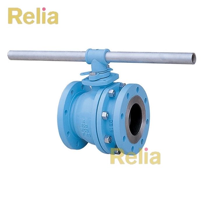
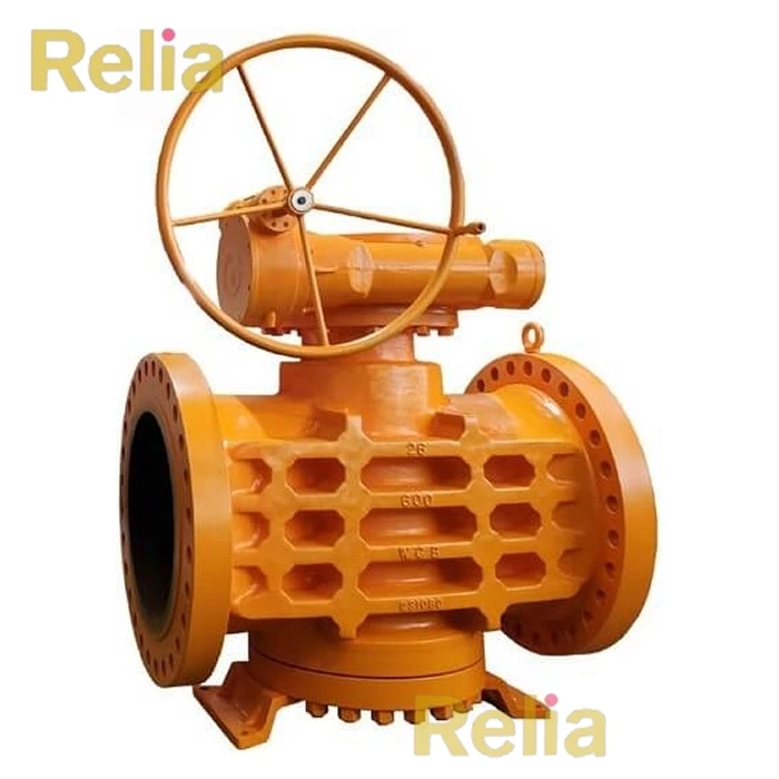
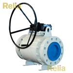


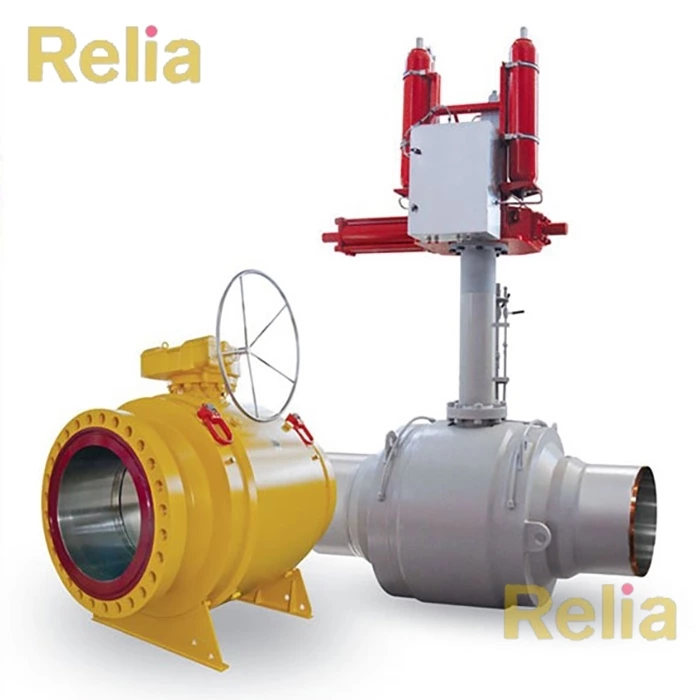
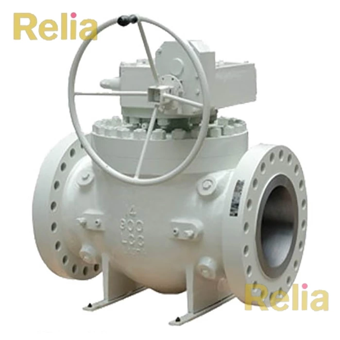
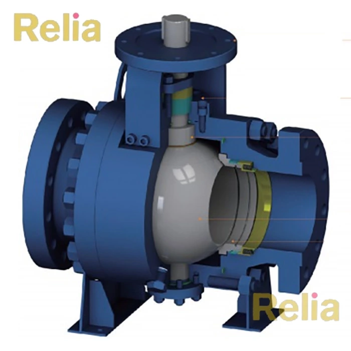
API 6D Ball Valves
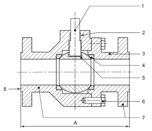
Ball valves shall be of solid one-piece spherical construction with a closure member that rotates on an axis perpendicular to the direction of flow.
NOTE - Typical configurations for API 6D ball valves with flanged or welding ends are shown, for illustration purposes only, in Figure B.2, Figure B.3, Figure B.4, and Figure B.5.
Key Parts
| No. | Part Name |
| 1 | stem |
| 2 | body cover |
| 3 | stem seal |
| 4 | body |
| 5 | seat ring |
| 6 | ball |
| 7 | body bolting |
| 8 | end connector |
| 9 | raised face |
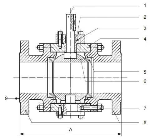
Figure B.3-API 6D Valve, Trunnion Ball Valve
Key Parts
| No. | Part Name |
| 1 | stem |
| 2 | stem seal |
| 3 | end connector |
| 4 | seat ring |
| 5 | ball |
| 6 | body bolting |
| 7 | body |
| 8 | raised face |
Figure B.2 - API 6D Valve, Floating Ball Valve
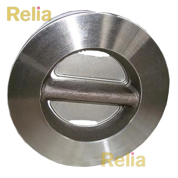
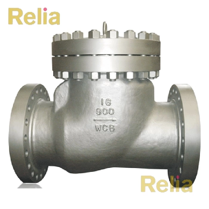
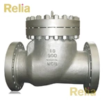
API 6D Check Valves
Check valves shall have a closure member that responds automatically to block fluid in one direction.
NOTE 1 Typical configurations for check valves are shown, for illustration purposes only, in Figure B.6, Figure B.7, Figure B.8,
Figure B.9, Figure B.10, Figure B.11 and Figure B.12.
NOTE 2 - Check valves can be of the wafer, axial flow, and lift type.
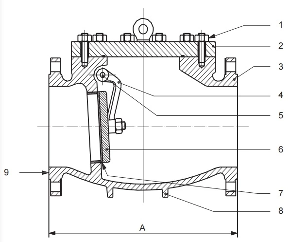
Key Parts
| No. | Part Name |
| 1 | cover bolting |
| 2 | cover |
| 3 | body |
| 4 | clapper disc arm |
| 5 | shaft |
| 6 | clapper disc |
| 7 | seat ring |
| 8 | support legs |
| 9 | raised face |
Figure B.11—API 6D Swing Check Valve
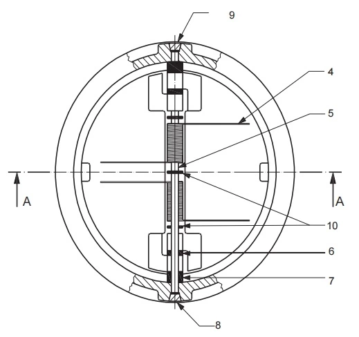
Key Parts
| No. | Part Name |
| 1 | body |
| 2 | closure plate |
| 3 | stop pin |
| 4 | spring |
| 5 | hinge pin |
| 6 | plate lug bearings |
| 7 | body lug bearings |
| 8 | stop pin retainers |
| 9 | hinge pin retainers |
| 10 | spring bearings |
| 11 | direction of flow |
Figure B.9—API 6D Dual Plate Wafer Check Valve
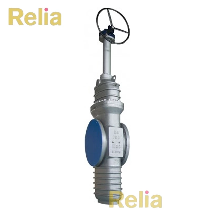
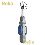
API 6D Gate Valves
Gate valves shall have a closure member that moves in a plane perpendicular to the direction of flow.
NOTE 1 The closure member can be constructed of one piece (slab-gate valve) or of two or more pieces (expanding-gate valve). Gate valves shall be provided with a back seat or secondary stem sealing feature in addition to the primary stem seal.
NOTE 2- Typical configurations for gate valves with flanged and welding ends are shown, for illustration purposes only,
in Figure B.13 and Figure B.1 4.
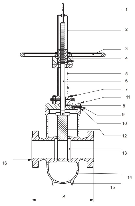
Key Parts
| No. | Part Name |
| 1 | stem indicator |
| 2 | stem enclosure |
| 3 | hand-wheel |
| 4 | yoke nut |
| 5 | yoke |
| 6 | stem |
| 7 | yoke bolting |
| 8 | stem packing |
| 9 | relief valve |
| 10 | bonnet |
| 11 | bonnet bolting |
| 12 | gate guide |
| 13 | gate assembly |
| 14 | seat ring |
| 15 | body |
| 16 | support ribs or legs |
| 17 | raised face |
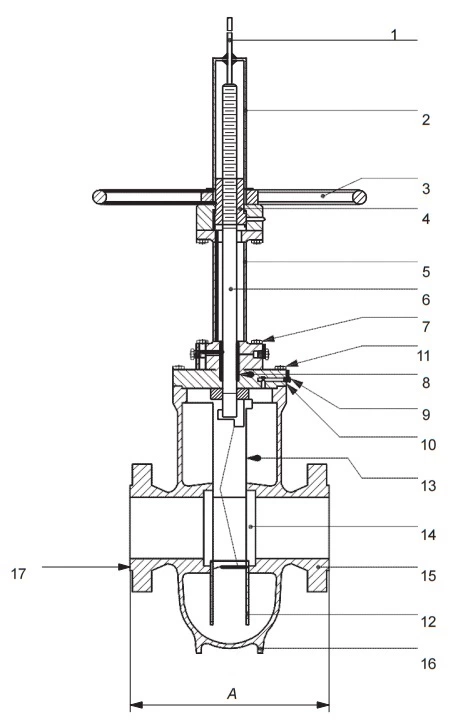
Figure B.13—Gate Valve (Expanding-gate/Rising-stem)
Key Parts
| No. | Part Name |
| 1 | stem indicator |
| 2 | stem enclosure |
| 3 | hand-wheel |
| 4 | yoke nut |
| 5 | yoke |
| 6 | stem |
| 7 | yoke bolting |
| 8 | stem packing |
| 9 | relief valve |
| 10 | bonnet |
| 11 | bonnet bolting |
| 12 | gate |
| 13 | seat ring |
| 14 | body |
| 15 | support ribs or legs |
| 16 | raised face |
Figure B.14—Gate Valve (Slab-gate/Through-conduit Rising-stem)
API 6D Plug Valves (Lubricated and Non-lubricated)
Plug valves shall have a cylindrical or conical closure member that rotates about an axis perpendicular to the
direction of flow.
NOTE A - typical configuration for a plug valves with flanged and welding ends is shown, for illustration purposes only, in Figure B.15.
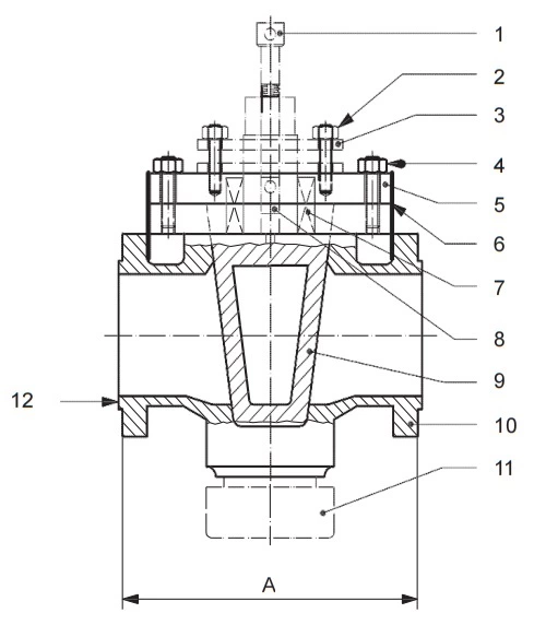
Key Parts
| 1 | lubricator screw |
| 2 | gland studs and nuts |
| 3 | gland |
| 4 | cover studs and nuts |
| 5 | cover |
| 6 | cover gasket |
| 7 | stem packing |
| 8 | lubricant check valve |
| 9 | plug |
| 10 | body |
| 11 | stop collar |
| 12 | raised face |
Figure B.15—Plug Valve
API 6D Axial Valves
Axial valves shall have a cylindrical closure member that moves on an axis parallel to the direction of flow.
NOTE A - typical configuration for axial valves with flanged or welding ends is shown, for illustration purposes only, in
Figure B.1 .
10.1 API 6D Valve Pressure Testing―General
10.1.1 Procedure
Written test procedures that identify test methodology, test durations and acceptance criteria shall be developed and maintained for all pressure testing performed in conformance to this specification.
Each valve shall be tested in the fully assembled condition to the manufacture’s procedures prior to shipment.
Pressure testing shall be carried out before external coating of the valve.
NOTE - If the valve has been previously pressure tested to the requirements of this specification, subsequent repeat hydrostatic and gas testing may be performed without removal of the valve external coating.
Testing shall be performed in the sequence as listed in order of 10.3 to 1 0.4.5. The backseat test that is only applicable to valves per 10.2 shall be performed either immediately before or immediately after the hydrostatic shell test in 10.3.
10.1.2 Duration and Acceptance Criteria
Shell test duration and acceptance criteria shall be based on the NPS of the valve ends.
Seat test duration and acceptance criteria shall be based on the bore diameter of the closure member. Seat test duration and acceptance criteria for noncircular opening valves shall be based on the NPS of the valve ends.
The hydrostatic test fluid shall be water and shall contain a corrosion inhibitor. The chloride content of test water in contact with austenitic and duplex stainless-steel wetted components of valves shall not exceed 30 µg/g (30ppm by mass). The chloride content in the test water shall be tested at least every 1 2 months and records shall be maintained in conformance with the documentation requirements of Section 14.
NOTE- The hydrostatic test fluid may have antifreeze (glycol) added at the discretion of the manufacturer.
10.1.3 Test Conditions
Valves shall be tested with the seating and sealing surfaces free from sealant except where the sealant is the primary means of sealing. A secondary seat and/or stem packing sealant system, if provided, shall not be used before or during testing.
All hydrostatic and gas shell tests specified shall be:
-performed with the valve unseated and partially open, or performed with the valve fully open, provided the body cavity is simultaneously filled and pressurized through a cavity connection.
The supply pressure shall be isolated from the valve during hydrostatic shell testing and shall be stabilized prior to the start of pressure testing duration. The stabilization criteria shall be documented in the manufacturer’s pressure testing procedure.
The pressure measuring device shall be installed in the test apparatus in such a manner that the device indicates the test pressure of the valve assembly. The minimum test pressures shall be maintained for the duration of the test and shall be held for the minimum test durations as specified in 10.2, 1 0.3 or 1 0.4.
10.1.4 Leakage
For hydrostatic or gas testing, visible leakage (see 3.1.58) shall be any release of test fluid observed during the pressure hold period. Test fluid released during the seat test pressure build-up or pressure bleed-down shall not be recognized as visible leakage. Visible leakage shall be observed directly, including through a window, or by video equipment.
If video equipment is used in place of direct observation, resolution and brightness shall be maintained to ensure the detection of possible leakage.
10.3 Hydrostatic Shell Test
10.3.1 Hydrostatic Shell Test Preparation, Method and Acceptance Criteria Valve ends shall be blocked and the closure member placed in the partially open position during the test.
When present, relief valves that release to the atmosphere shall be removed and their connection points plugged. Internal non-return valve shall be installed on sealant injection ports without the injection fitting.
The test pressure for the hydrostatic shell test shall be a minimum of 1.5 times the pressure rating conforming to 4.3 for material at 100 °F (38 °C) based on the valve end connector material. The test duration shall conform to Table 9 based on the valve end connector size.
Table 9—Minimum Duration of Hydrostatic Shell Tests
| Valve Size | Test Duration | |
| NPS (Inch) | DN | (minutes) |
| ≤ 4 | ≤ 100 | 2 |
| 6 to 10 | 150 to 250 | 5 |
| 12 to 18 | 300 to 450 | 15 |
| 20 and larger | 500 and larger | 30 |
10.4 Seat Test
10.4.1 Hydrostatic Seat Test Preparation, Method and Acceptance Criteria Lubricants or sealants shall be removed from seats and closure member sealing surfaces except where the lubricant or sealant is the primary means of sealing.
NOTE See K.1 4 for guidance on performing alternative hydrostatic seat testing.
The test pressure for all seat tests shall be a minimum of 1 .1 times the pressure rating conforming to 4.3 for material at 100 °F (38 °C) based on the valve end connector material. The test duration shall conform to Table 10 based on the valve end connector size.
Table 10—Minimum Duration of Hydrostatic Seat Tests
| Valve Size | Test Duration | |
| NPS (Inch) | DN | (minutes) |
| ≤ 4 | ≤ 100 | 2 |
| 6 to 18 | 150 to 450 | 5 |
| 20 and larger | 500 and larger | 10 |
Seat leakage shall be monitored from the downstream side of the seat when under hydrostatic seat test.
The acceptance criteria for leakage shall be as follows:
― For soft-seated valves and lubricated plug valves: leakage shall not exceed ISO 5208, Rate A (no visible leakage for the duration of the test at test pressure).
― For metal-seated valves, other than check valves: leakage shall not exceed ISO 5208, Rate CD.
NOTE The test procedures for various types of block valve are specified in 1 0.4.3.
― For metal-seated check valves: leakage shall not exceed ISO 5208, Rate E.
On completion of hydrostatic seat testing, parts such as drain plugs and cavity-relief valves, shall be fitted in conformance with the manufacturer’s documented procedures.
10.4.3 Hydrostatic Seat Test—Block Valves
10.4.3.1 Unidirectional
With the valve half-open, the valve and its cavity shall be entirely filled with test fluid. The valve shall then be closed, and the test pressure applied to the appropriate end of the valve.
Leakage from the upstream seat shall be monitored via the valve body cavity vent or drain connection, where provided. For valves without a body cavity vent or drain connection or for downstream-seated valves, seat leakage shall be monitored at the respective downstream end of the valve (i.e., the valve end downstream of the pressurized test fluid).
10.4.3.2 Bidirectional
With the valve half-open, the valve and its cavity shall be entirely filled with test fluid. The valve shall then be closed, and the test pressure applied successively to both ends of the valve.
Seat leakage shall be monitored from each seat via the valve body cavity vent or drain connection, where provided. For valves without a body cavity vent or drain connection or for downstream-seated valves, seat leakage shall be monitored from the respective downstream end of the valve.
10.4.4 Certification of Cavity Relief Valve
If provided, the cavity relief valve (to the atmosphere) shall have the pressure set, tested, and certified to relieve to atmospheric pressure at the specified pressure by the relief-valve supplier or by the valve manufacturer.
The set pressure of relief valves shall be between 1.1 and 1.33 times the valve pressure rating conforming to 4.3 for material at 250 °F (1 21 °C). The reseat pressure shall not be less than 1.05 times the valve pressure rating conforming to 4.3 for material at 250 °F (1 21 °C). The manufacturer shall specify the set pressure of relief valves for temperatures above 250 °F (121 °C).

Leave Us Your Info
Could you please kindly fulfill the following information when enquiring:
Valve type (ball, gate, globe, check etc.), valve size, pressure class, valve material, and end connection (flanged, butt welding etc.)