API 6D Valve Testing Requirements
API 6D Pressure test requirements inluding test procedure, test pressure and durating for gate valve, ball valve, check valve and plug valves.
10.1 General
Each valve shall be tested in accordance with this clause prior to shipment. The purchaser shall specify which particular supplementary tests in Annex C shall be performed, together with the frequency of testing.
Testing shall be performed in the sequence used in this clause for specifying the test requirements. Shell pressure testing shall be carried out before painting of the valves.
Test fluids shall be fresh water which may contain a corrosion inhibitor and, by agreement, antifreeze. The chloride content of test water for austenitic and ferritic-austenitic (duplex) stainless-steel body/bonnet valves shall not exceed 30 µg/g (30 ppm).
Valves shall be tested with the seating and sealing surfaces free from sealant except where the sealant is the primary means of sealing.
Tests specified with the valve half-open may also be performed with the valve fully open provided the body cavity is simultaneously filled and pressurized through a cavity connection.
Methods for monitoring pressures and/or leakage shall be adequate also when valve body connections are not available for direct monitoring.
A sufficient stabilization period shall be allowed for all pressure tests.
Pressure testing shall be performed in accordance with documented procedures.
10.2 Stem backseat test
Unless otherwise agreed, stem backseat testing shall be performed prior to shell testing.
Where a valve has a stem backseat feature, testing of the backseat shall commence with the seat free. Self-energized packing or seals shall be removed unless a test port is provided for this test.
The valves shall be filled with the ends closed off and the obturator in the partially open position until leakage of the test fluid around the stem is observed. The backseat shall then be closed and a minimum pressure of 1,1 times the pressure rating determined in accordance with 6.1 for material at 38°C (100°F) is applied for the duration specified in Table 9.
Monitoring for leakage shall be through a test access port or by monitoring leakage around the loosened packing.
No visible leakage is permitted at this test pressure.
Table 9—Minimum duration of stem backseat tests
| Valve size | Test duration (minutes) | |
| DN (mm) | NPS (inches) | |
| ≤100 | ≤4 | 2 |
| ≥150 | ≥6 | 5 |
10.3 Hydrostatic shell test
Hydrostatic shell testing shall be performed on the fully assembled valve prior to painting.
Valves shall be closed off and the obturator placed in the partially open position during the test. If specified by the purchaser, the method of closing the ends shall permit the transmission of the full-pressure force acting on the end blanks to the valve body. Where present, external relief valves shall be removed and their connections plugged.
The test pressure shall be 1,5 or more times the pressure rating determined in accordance with 6.1 for material at 38°C (100°F). The duration shall not be less than that specified in Table 10.
Table 10—Minimum Duration of Hydrostatic Shell Tests
| Valve Size | Test Duration | |
| NPS (Inch) | DN | (minutes) |
| ≤ 4 | ≤ 100 | 2 |
| 6 to 10 | 150 to 250 | 5 |
| 12 to 18 | 300 to 450 | 15 |
| 20 and larger | 500 and larger | 30 |
No visible leakage is permitted during the hydrostatic shell test.
After hydrostatic shell testing, external relief valves shall be (re)fitted to the valve. The connection to the valve body shall be tested at 95% of the set pressure of the relief valve for 2 minutes for valve sizes up to and including DN 100(NPS 4), and 5 minutes for valve sizes DN 150 (NPS 6) and larger. The relief valve connection shall be free of visible leakage during this period.
Where provided, the external relief valve shall be set to relieve at the specified pressure and tested. The set pressure of relief valves shall be between 1,1 and 1,33 times the valve pressure rating determined in accordance with 6.1 for material at 38°C (100°F).
10.4 Hydrostatic seat test
10.4.1 Alternative test
High-pressure gas seat testing in accordance with clause C.4 may be performed in lieu of the hydrostatic seat test described below.
10.4.2 Preparation
Lubricants shall be removed from seats and obturator sealing surfaces except, by agreement, for assembly lubricants for metal-to-metal contact sufaces.
10.4.3 Test pressure and duration
The test pressure for all seat tests shall not be less than 1,1 times the pressure rating determined in accordance with 6.1 for material at 38°C (100°F). The test duration shall be in accordance with Table 11.
Table 11—Minimum Duration of Hydrostatic Seat Tests
| Valve Size | Test Duration | |
| NPS (Inch) | DN | (minutes) |
| ≤ 4 | ≤ 100 | 2 |
| 6 to 18 | 150 to 450 | 5 |
| 20 and larger | 500 and larger | 10 |
10.4.4 Acceptance criteria
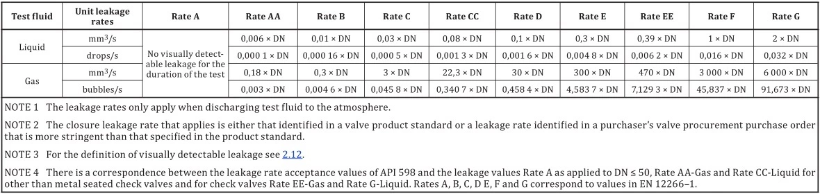
Leakage for soft-seated valves and lubricated plug valves shall not exceed ISO 5208 Rate A (no visible leakage).
For metal-seated valves the leakage rate shall not exceed ISO 5208 Rate D, except that the leakage rate during the seat test in 10.4.5.5.2 shall not be more than two times ISO 5208 Rate D unless otherwise specified. The test procedures for various types of block valve are given in 10.4.5.
ISO 5208 clousure test maximum allowable leakage rate
10.4.5 Test procedures for block valves (Ball, Gate, Plug Valves)
10.4.5.1 Uni-directional
With the valve half-open, the valve and its cavity shall be completely filled with test fluid. The valve shall then be closed and the test pressure applied to the appropriate end of the valve.
Leakage from each seat shall be monitored via the valve body cavity vent or drain connection. For valves without a body cavity connection, seat leakage shall be monitored from each seat at the respective downstream end of the valve (the valve end downstream of the pressurized test fluid).
10.4.5.2 Bi-directional
With the valve half-open, the valve and its cavity shall be completely filled with test fluid. The valve shall then be closed and the test pressure applied successively to both ends of the valve.
Seat leakage shall be monitored from each seat via the valve body cavity vent or drain connection. For valves without a body cavity vent or drain connection, seat leakage shall be monitored from the respective downstream end of the valve.
10.4.5.3 Twin-seat, both seats bi-directional
Each seat shall be tested in both directions.
Cavity relief valves shall be removed if fitted. The valve and cavity shall be filled with test fluid, with the valve half-open, until the test fluid overflows through the cavity relief connection.
To test for seat leakage in the direction of the cavity, the valve shall be closed. The test pressure shall be applied successively to each valve end to test each seat separately from the upstream side. Leakage shall be monitored via the valve cavity pressure relief connection.
Thereafter, each seat shall be tested as a downstream seat. Both ends of the valve shall be drained and the valve cavity filled with test fluid. Pressure shall then be applied whilst monitoring leakage through each seat at both ends of the valve.
10.4.5.4 Twin-seat for a valve, one seat uni-directional and the other seat bi-directional
Uni-directional seat
With the valve half-open, the valve and the test cavity shall be completely filled with test fluid until fluid overflows though the valve cavity vent connection. The valve shall then be closed and the vent valve on the test closure opened to allow fluid to overflow, or the test closure on the downstream end of the valve removed. The test pressure shall then be applied to the upstream end (uni-directional seat end) and leakage monitored from the cavity connection. If leakage is also occurring through the downstream seat, the upstream seat leakage shall be taken as the sum of the leakage measured from the cavity and the downstream connections.
Bi-directional seat
The test in 10.4.5.4.1 shall be repeated to test the bi-directional seat in its upstream-sealing direction.
To test the bi-directional seat in its downstream-sealing direction, both ends of the valve shall be blanked off. With the valve half-open, the valve shall be completely filled with test fluid and pressurized to the test pressure. The valve shall then be closed and test fluid allowed to overflow from a connection on the test closure fitted to the end of the valve at the bi-directional seat end (i.e., downstream of the bi-directional seat). The test pressure shall be maintained on the cavity connection whilst monitoring seat leakage of the bi-directional seat at the overflow connection on the downstream test closure.
10.4.5.5 Double-block-and-bleed valves
Single-seat test
With the valve half-open, the valve and its cavity shall be completely filled with test fluid. The valve shall then be closed and the valve body vent valve opened to allow excess test fluid to overflow from the valve cavity test connection. The test pressure shall then be applied to one end of the valve and the pressure released at the other end. This test shall be repeated for the other valve end.
Seat tightness shall be monitored during each test via overflow from the valve cavity connection.
Double-block seat test
With the valve half-open, the valve and its cavity shall be completely filled with test fluid. The valve shall then be closed and the valve body vent valve opened to allow excess test fluid to overflow from the valve cavity test connection. The test pressure shall be applied simultaneously from both valve ends.
Seat tightness shall be monitored via overflow through the valve cavity connection.
The tests in 10.4.5.5 may be performed in any order by the manufacturer.
10.4.5.6 Check valves
The pressure shall be applied in the direction of the required flow blockage.
10.4.5.7 Installation of body connections after testing
Pressure-containing parts, such as vent/or drain plug(s) and cavity relief valves, shall be fitted, on completion of testing, in accordance with documented procedures.
10.5 Draining
Valves shall be drained of test fluids and, where applicable, lubricated before shipment.