API RP 621: Reconditioning of Metallic Gate, Globe, and Check Valves
1 - Scope
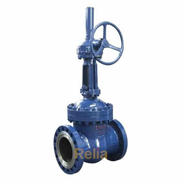
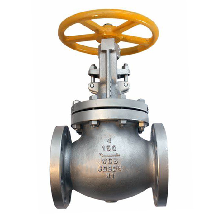
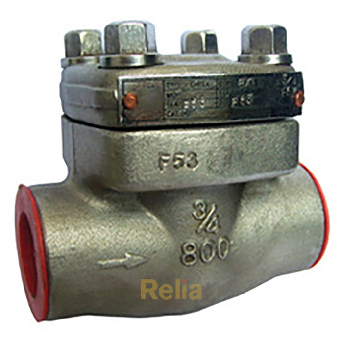
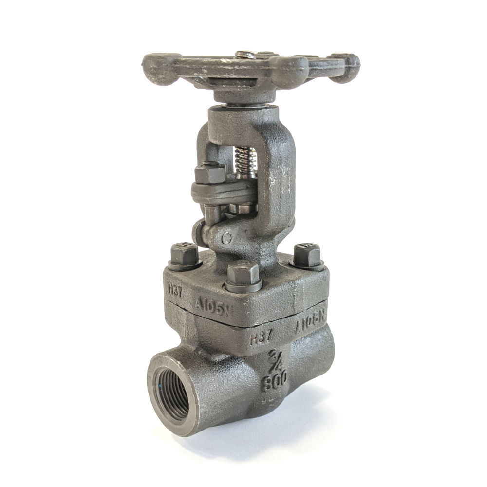
1.1 API RECOMMENDED PRACTICE 621 provides guidelines for reconditioning heavy wall (API 600, API 623, and API 594 type) carbon steel, ferritic alloy (up to 9 % Cr), stainless steel, and nickel alloy gate valve, globe valve, and check valves for ASME pressure classes 1 50, 300, 400, 600, 900, 1 500, and 2500. Guidelines contained in this RP apply to flanged and butt weld cast or forged valves.
1.2 It is an expectation of this RP that a contractual agreement shall be established between the Owner and the valve reconditioning facility. The reconditioning facility may be original equipment manufacturer (OEM) owned/operated, or directly associated and approved by the OEM. At the Owner’s option, an independent facility may be used. The Owner shall determine that the facility selected for valve reconditioning has a documented and established working Quality Assurance Program. The Quality Assurance Program should include the essential elements described in the ISO 9001 standard.
1.3 This RP does not cover reconditioning or remanufacturing of used or surplus valves intended for resale. The only intent of this RP is to provide guidelines for refurbishing an end user’s (Owner) valves for continued service in the Owner’s facility. Valves reconditioned or remanufactured to this RP may not meet API Standard requirements for new valves. The correct application of a valve reconditioned to this RP remains the responsibility of the Owner.
6 - Repair of Valve Parts
6.1 General
6.1.1 Welding
6.1.1.1 Welding procedures and welders shall be qualified in accordance with Section IX of the ASME Boiler and Pressure Vessel Code.
6.1.1.2 Welding procedures and PQRs shall be submitted to the Owner for approval prior to the start of welding.
6.1.1.3 Weld metal buildup and weld metal repairs, including any required postweld heat treatment, shall be performed in accordance with the approved procedures.
6.1.2 Nondestructive Examination (NDE)
6.1.2.1 Welds, other than tack welds, shall be examined by the liquid penetrant method or by the NDE method specified by the Owner.
6.1.2.2 NDE of parts and/or weld repairs shall be done in accordance with Owner-approved NDE procedures and acceptance criteria.
6.1.2.3 SNT-TC-1 A Level II technicians certified for the procedures per ASME Section V shall evaluate NDE results.
6.1.3 Replacement Parts and Material
6.1.3.1 Sources of replacement parts shall be one or more of the following in preferential order:
6.1.3.1 Sources of replacement parts shall be one or more of the following in preferential order:
a) parts purchased from the OEM or other OEM-approved source;
b) parts salvaged from scrapped valves from the same valve manufacturer and with matching identification;
c) parts manufactured in the reconditioning facility, when approved by the Owner.
6.1.3.2 Material used to manufacture replacement parts in the reconditioning facility shall be as specified by the Owner or the following in preferential order.
a) If the Owner does not specify material, the material used (including heat treatment if applicable) shall be the material used by the original valve manufacturer and shall comply with the requirements of the referenced standard.
b) Changes in material group, such as 1 3CR to austenitic stainless steel, require approval of the Owner.
c) Verification of the specific material used and its source shall be part of the required documentation.
6.1.3.3 As a minimum, the following components shall be replaced:
a) soft seats;
b) bonnet and cover bolting;
c) packing;
d) gaskets;
e) grease fittings.
6.2 Inspection of Valve Parts
6.2.1 General
6.2.1.1 Valve parts shall be inspected to determine their acceptability for re-use and/or extent of required repair.
6.2.1.2 Criteria for acceptability and extent of repair shall be the component’s ability to meet the Owner’s expectation for continued service in his/her facility.
6.2.2 Threaded Parts
6.2.2.1 Threaded parts shall be visually inspected for gross defects, such as missing or incomplete threads, defective thread profile, torn or ruptured surfaces, and cracks.
6.2.2.2 Surface texture of threaded parts shall be evaluated by visual or tactile comparison with texture specimens or surface measurement equipment.
6.2.2.3 Visual inspection shall be made without magnification. Thread acceptability criteria shall be specified in the relevant ASTM, ASME, or API standard.
6.3 Handwheel Nut
6.3.1 Handwheel nut shall be visually inspected for wear or excessive corrosion of the threads or contact area.
6.3.2 If the handwheel nut is defective, it shall be repaired or replaced.
6.3.3 If the handwheel nut is locked into place with a setscrew or some other device, the locking mechanism shall be in place and fully functional.
6.4 Handwheel
6.4.1 Handwheel shall be visually inspected for worn, bent, or broken spokes and rim.
6.4.2 Handwheel shall be inspected to verify proper engagement to the stem yoke nut. If the valve does not have a yoke nut, the handwheel shall be inspected to verify proper engagement to the stem.
6.4.3 A defective handwheel shall be repaired by the appropriate repair method for the defect: bent spokes, hub, or rim may be straightened by pressing. Broken spokes or rim (if made of a weldable grade material) may be weld repaired.
6.4.4 If the defect(s) cannot be repaired, the handwheel shall be scrapped and replaced with one of similar size and material.
6.4.5 All parts of the handwheel and any repairs shall be free of burrs, metal splinters, and sharp metal edges.
6.5 Yoke
6.5.1 Yoke shall be visually inspected for defects and for proper alignment of the stem through the stem nut, packing chamber, backseat bushing, and wedge connection.
6.5.2 Defects shall be repaired by generally accepted repair procedures, such as welding or machining.
Annex B
(normative)
Stem Packing
B.1 - Scope
This annex covers requirements for materials, design, and installation for stem packing for valves being reconditioned in accordance with this RP.
B.2 - Types of Packing
Type A - Carbon or graphite wiper rings having a yarn property carbon assay of 98 % minimum and with corrosion inhibitor applied at the time of manufacture.
Type B - Graphite die-formed rings made of 98 % pure carbon graphite or better and with corrosion inhibitor. After die forming, the rings shall have a minimum density of 70 lb/ft 3 .
Type C - PTFE V-rings incorporating a heavy wall and heel section. A minimum of two pressure rings together with male and female adapters shall be used.
Type D - Braided continuous filament (e.g. PTFE, graphite).
Type E - Owner-specified packing configuration.
B.3 - Materials
B.3.1 Packing material shall be asbestos free.
B.3.2 Leachable chloride content of the rings shall be limited to 1 00 ppm maximum.
B.3.3 Total sulfur in the rings shall be 1 000 ppm maximum.
B.3.4 Unless otherwise specified, packing shall contain no binders, lubricants, or other additives.
B.4 - Spacers or Bushings
Spacers or bushings used to fill stuffing boxes of excessive depth on gate and globe valves shall:
a) be compatible with the stem material;
b) be made of carbon, or a material approved by the Owner, that is equivalent to the valve bonnet material or of a material with a greater corrosion and temperature resistance than the bonnet material and with a hardness at least 50 HB different than the stem hardness except for 300 series stainless. The use of carbon bushings shall be limited to packing chambers that have a flat bottom;
C) conform to the dimensional clearances in Figure B.1 .
B.5 - Lantern Rings
B.5.1 If a lantern ring is specified in the stuffing box for an external connection, it shall be aligned with the external connection or placed in accordance with the Owner’s instructions.
B.5.2 Packing rings immediately above and immediately below the lantern shall be Type A wiper rings; or if Vee ring packing is used, a female adapter shall be immediately below and a male adapter shall be immediately above the lantern ring.
B.5.3 Figure B.2 shows this diagrammatically.
B.6 - Flexible Graphite Packing for Block Valves Refer to Figure B.3.
B.7 - PTFE Vee Ring Packing for Block Valves Refer to Figure B.4.
B.8 - Braided Packing for Block Valves Refer to Figure B.5
Annex C
(normative)
Tests
C.1 - Scope
This annex covers requirements for testing of valves being reconditioned in accordance with this RP.
C.2 - General
C.2.1 Unless a more restrictive test is specified by the Owner, test pressures, test durations, test fluids, and leakage rates shall conform to API 598 to verify the pressure integrity of the valve body and the valve seat(s).
C.2.1.1 During seat testing for gate valves, the valve body cavity shall be pressurized by allowing the test medium to flow through the valve as the wedge is being closed onto the seats.
C.2.1.2 Preferably, the seat test shall be performed with the valve stem in the horizontal position, the valve bore in the vertical position, and one side of the valve open.
C.2.1.3 If a valve must be tested with the stem in the vertical position, double flanging both sides of the valve and using a pipe stand is permitted for the high-pressure seat tests. Double flanging both sides of the valve and using a bubbler is permitted for the low-pressure air seat test when approved by the Owner.
C.2.2 The additional bonnet and stem seal leakage test is required, unless waived by the valve Owner.
a) The test fluid shall be either helium or methane, as specified by the valve Owner.
b) The test temperature shall be between 5 °C (41 °F) and 50 °C (1 22 °F).
c) Open the valve halfway and pressurize to 1 00 psig.
d) Fully open and close the pressurized valve three (3) times and leave in the half open position.
e) After a minimum duration of 5 minutes, measure the bonnet and stem seal leakage. The valve stem and bonnet shall be encapsulated during this testing. Monitor leakage for a minimum of 1 minute or until leakage stabilizes.
1 ) Stem seal leakage shall not exceed 1 00 ppmv (methane) or 3.0e-3 atm cc/sec (helium).
2) Bonnet leakage shall not exceed 50 ppmv (methane) or 1 .5e-3 atm cc/sec (helium).
C.3 - Test Equipment
C.3.1 Test equipment that may conceal or reduce disqualifying conditions from being easily detected shall not be used.
C.3.2 Gauges used for pressure tests shall have been calibrated to the National Bureau of Standards within the previous year and shall be functioning properly at the time of the test.
C.3.3 Equipment used for pressure tests shall not apply external forces that affect seat leakage. If an end-clamping test fixture is used, the Reconditioner shall demonstrate that the fixture does not affect the seat-sealing capability of the valve being tested.
Related Product:
8 inch ball valve, 26 inch ball valve, 28 inch ball valve, 30 inch ball valve