API 6D: Specification for Valves in the petroleum and natural gas industries
API 6D defines the requirements for the design, manufacturing, materials, welding, quality control, assembly, testing, marking, documentation and process controls of axial valve, ball valve, check valve, gate valve, plug valves for application in the petroleum and natural gas industries.
This specification is not applicable to valves for pressure Class 400 and pressure ratings exceeding Class 2500.
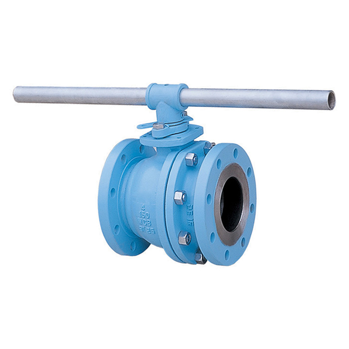
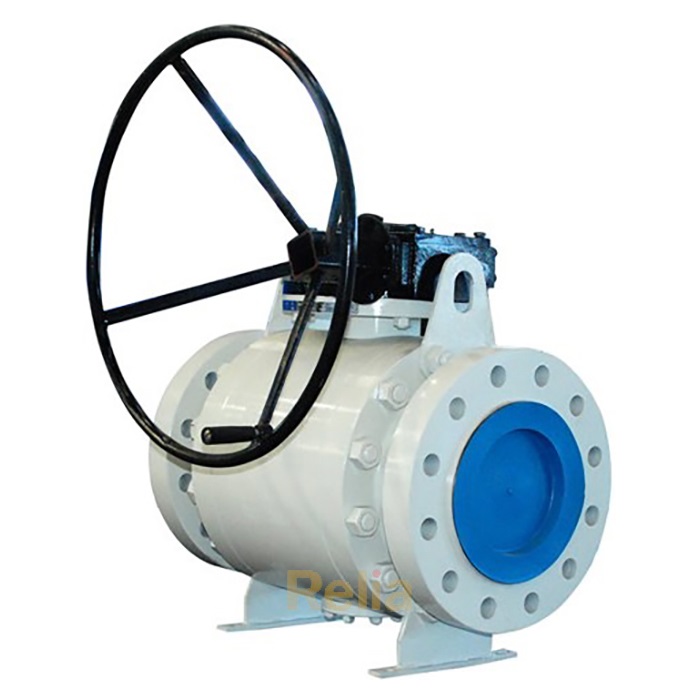
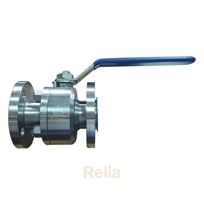
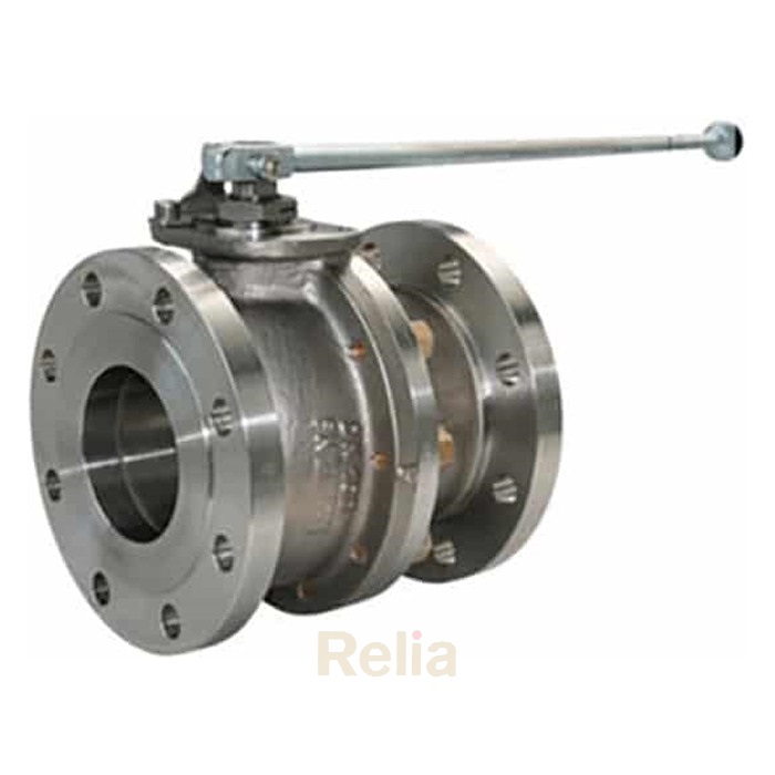
Relia API 6D Ball Valve
API 6D certified, bubble tight shut off, 100% tested as API 6D/API 598 before shippment
APPLICATION, CONFIGURATION and PERFORMANCE
4.1 Valve Types
4.1.1 General
This Specification shall apply to the following:
― axial valves
― check valves
― gate valves
― plug valves
NOTE- The nomenclature used in this Specification for typical equipment is shown in Figure B.1 thru B.1 5.
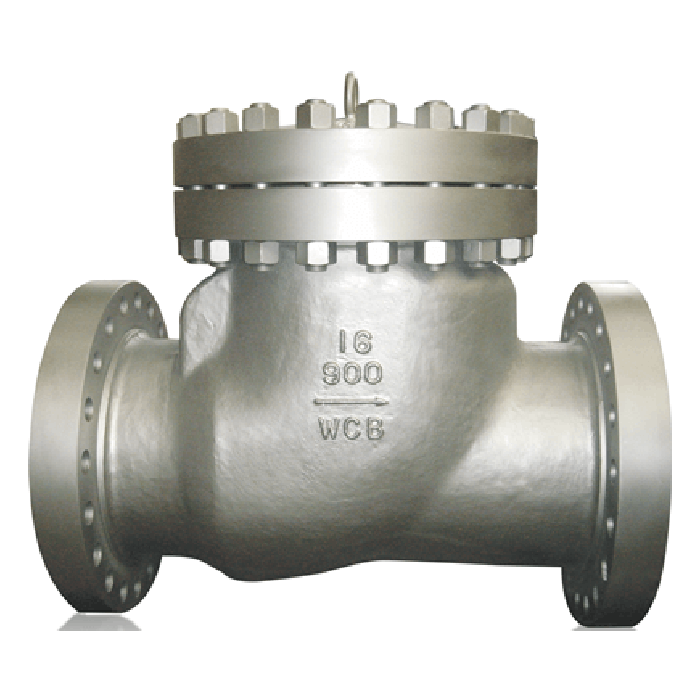
Relia API 6D Check Valve
API 6D design, swing check, full port, 100% tested as API 6D/API 598 before shippment
4.1.2 Axial Valves
Axial valves shall have a cylindrical closure member that moves on an axis parallel to the direction of flow.
NOTE- A typical configuration for axial valves with flanged or welding ends is shown, for illustration purposes only, in
Figure B.1 .
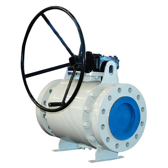
4.1.3 Ball Valves
Ball valves shall be of solid one-piece spherical construction with a closure member that rotates on an axis perpendicular to the direction of flow.
NOTE- Typical configurations for ball valves with flanged or welding ends are shown, for illustration purposes only, in Figure
B.2, Figure B.3, Figure B.4, and Figure B.5.
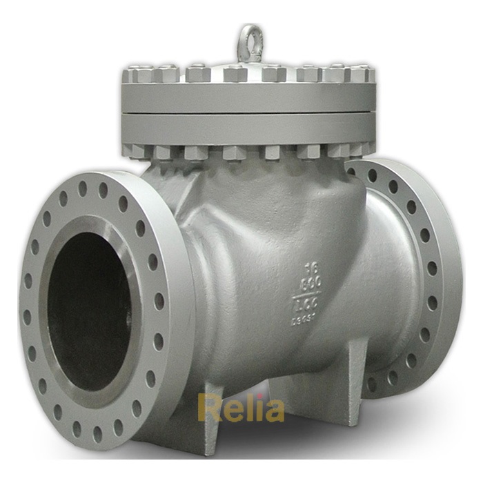
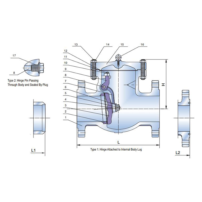
4.1.4 Check Valves
Check valves shall have a closure member that responds automatically to block fluid in one direction.
NOTE 1- Typical configurations for check valves are shown, for illustration purposes only, in Figure B.6, Figure B.7, Figure B.8,
Figure B.9, Figure B.10, Figure B.11 and Figure B.12.
NOTE 2- Check valves can be of the wafer, axial flow, and lift type.
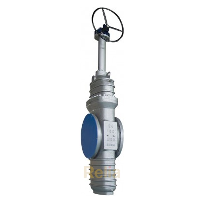
4.1.5 Gate Valves
Gate valves shall have a closure member that moves in a plane perpendicular to the direction of flow.
NOTE 1- The closure member can be constructed of one piece (slab-gate valve) or of two or more pieces (expanding-gate valve).
Gate valves shall be provided with a back seat or secondary stem sealing feature in addition to the primary stem seal.
NOTE 2- Typical configurations for gate valves with flanged and welding ends are shown, for illustration purposes only,
in Figure B.13 and Figure B.1 4.
4.1.6 Plug Valves (Lubricated and Non-lubricated)
Plug valves shall have a cylindrical or conical closure member that rotates about an axis perpendicular to the direction of flow.
NOTE A- typical configuration for a plug valves with flanged and welding ends is shown, for illustration purposes only, in Figure B.15.
4.3 Pressure and Temperature Rating
4.3.1 Standard Valves
Valves covered by this specification shall be furnished in one of the following pressure classes (see 3.1.36):
― Class 150
― Class 300
― Class 600
― Class 900
― Class 1500
― Class 2500
Pressure–temperature ratings for class-rated valves shall conform to the rating table for the applicable material group per ASME B16.34 or for carbon steel per MSS-SP 44.
The pressure–temperature rating applied shall be based on the material group of the valve end connector. Where the valve ends are made from material in two different groups, the material with the lower pressure–temperature.
NOTE- Different material or material forms may be used for body and bonnet or cover parts within the same valve.
All metallic pressure-containing and pressure-controlling parts shall be designed to meet the identified valve pressure–temperature rating.
The manufacturer shall determine any limits on the maximum allowable operating pressure and shall identify the minimum and maximum design temperatures resulting from the nonmetallic parts used.
4.3.2 Non-standard Valves - Intermediate Pressures and Temperatures
Intermediate pressure and temperature ratings shall conform to K.2.
NOTE- Intermediate pressure and temperature rating cannot apply to valve designs with ASME flanged ends (see K.2)
Pressure–temperature ratings for valves made from materials not listed in ASME B16.34 shall be determined using the methods defined in ASME B16.34 Appendix B up to the temperature limitation of the valve.
Related Product:
8 inch ball valve, 26 inch ball valve, 28 inch ball valve, 30 inch ball valve